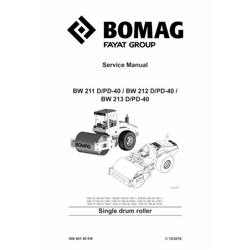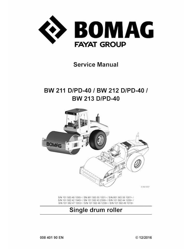
BOMAG BW211, BW212, BW213 D-40, PD-40 single drum roller pdf service manual
Format: PDF
Pages: 1392
File size: 86.35 MB
Language: English
Models: BW211 D/PD-40, BW212 D/PD-40, BW213 D/PD-40

Table of Contents for BOMAG-00840190EN-l16 manual
- Table of contents
- 1 General
- 1.1 Introduction
- 1.2 Concerning your safety
- 1.3 Notes on repair
- 1.4 Fuels and lubricants
- 1.5 List of fuels and lubricants
- 2 Overview of machine
- 2.1 Diesel engine
- 2.2 Travel / vibration pump
- 2.3 Drum
- 3 Technical data
- 3.1 Technical data BW 211 D/PD-40
- 3.2 Technical data BW 212 D/PD-40 (58243, 58248, 58356)
- 3.3 Technical data BW 212 D-40 (58348, 58356)
- 3.4 Technical data BW 213 D/PD-40
- 3.5 Additional technical data
- 4 Electric systems
- 4.1 Table of fuels and lubricants
- 4.2 Central electrics
- 4.3 Fuse assignment
- 4.4 Operator's stand
- 4.5 Wiring
- 4.6 Starting the engine with jump leads
- 4.7 Proximity switches on travel lever, B13 and B14
- 4.8 Differential pressure switch for hydraulic oil filter, B21
- 4.9 Level sensor in diesel tank, R03
- 4.10 Float switch, coolant tank, B55
- 4.11 Air filter vacuum switch, B03
- 4.12 Sensor for water in fuel, B124
- 4.13 Fuel pre-heating, R79
- 4.14 Oil pressure switch, B06
- 4.15 Coolant temperature switch, B30
- 4.16 Boost fuel solenoid valve, Y01
- 4.17 Solenoid actuator to shut down the engine, Y13
- 4.18 Engine solenoid actuator, Y120
- 4.19 Charge control light, engine tachometer
- 4.20 Heating flange on engine, R19
- 4.21 MESSX, A83
- 4.22 Acceleration transducer, B62
- 4.23 Control unit for air conditioning, A108
- 4.24 Module for seat contact monitoring, A68
- 4.25 Vibration module, K04
- 4.26 Speedometer module, A05
- 4.27 Telemecanique switch
- 4.28 Deutsch plug, series DT and DTM
- 4.29 Magnetic coil plug
- 4.30 Inspection and maintenance work
- 5 Diesel engine
- 5.1 Diesel engine, general
- 5.2 Service side
- 5.3 Starter side
- 5.4 Lubrication oil circuit
- 5.5 Coolant circuit
- 5.6 Replacing the thermostat
- 5.7 Fuel supply
- 5.8 Injection system
- 5.9 Injection pump replacement during service
- 5.10 Injection valve replacement during service
- 5.11 Checking / repairing injection valves
- 5.12 Checking the compression
- 5.13 Inspection and maintenance work
- 6 Hydraulic system
- 6.1 Overview of travel/vibration pump connections
- 6.2 Open and closed hydraulic circuit
- 6.3 Hydraulic units
- 6.4 Charge circuit
- 6.5 Travel circuit
- 6.6 Vibration circuit
- 6.7 Steering circuit
- 6.8 Tests and adjustments
- 6.9 Flushing and bleeding
- 6.10 Inspection and maintenance work
- 7 Air conditioning
- 7.1 Overview
- 7.2 Physical principles
- 7.3 Refrigerant R134a
- 7.4 Compressor oil / refrigeration oil
- 7.5 Working principle of the air conditioning system
- 7.6 Monitoring devices
- 7.7 Description of components
- 7.8 Compressor
- 7.9 Emptying in case of repair
- 7.10 Drying and evacuation
- 7.11 Filling instructions
- 7.12 Steam table for R134a
- 7.13 Inspection and maintenance work
- 8 Cabin assembly before initial commissioning
- 8.1 Preparations
- 8.2 Cabin assembly
- 8.3 Final function tests and checks
- 9 Replacing the cab window panes
- 9.1 Assembly of window panes
- 9.2 Auxiliary materials
- 9.3 Removing and installing the window pane
- 10 Oscillating articulated joint
- 10.1 Overview oscillating articulated joint
- 10.2 Removing and installing the oscillating articulated joint
- 10.3 Dismantling the oscillating articulated joint
- 10.4 Assembling the oscillating articulated joint
- 11 Drum
- 11.1 Assembly of padfoot shell
- 11.2 Overview drum
- 11.3 Removing and installing the drum
- 11.4 Dismantling the drum
- 11.5 Dismantling and assembling the change-over weight
- 11.6 Assembling the drum
- 11.7 Changing the rubber buffers, adjusting the pretension
- 11.8 Inspection and maintenance work
- 12 Drive axle
- 12.1 Drive axle
- 12.2 Checks prior to start up
- 12.3 Every 250 operating hours
- 12.4 Every 1000 operating hours
- 12.5 As required
- 13 Troubleshooting
- 13.1 Preliminary remarks
- 13.2 Emergency procedures
- 13.3 Troubleshooting, electrical systems
- 13.4 Troubleshooting, diesel engine
- 13.5 Trouble shooting, hydraulics
- 13.6 Trouble shooting, air conditioning system
- 14 Disposal
- 14.1 Final shut-down of machine
- 15 Special tools
- 15.1 Special tools, electrics
- 15.2 Special tools, hydraulic system
- 15.3 Special tools for oscillating articulated joint
- 15.4 Special tools, drum
- 16 Index
- Appendix
- A Supplier documentation
- B Circuit diagrams
High-Quality PDF Service Manuals for Professional Repair
Our Service Manuals are comprehensive digital products delivered in convenient PDF formats, providing the exact technical data required to maintain, repair, and troubleshoot your equipment. Whether you are a fleet owner or a professional technician, having a dedicated PDF service manual ensures you have instant access to factory-spec information.
What is Included in Our Service Manuals?
Every repair and service manual we provide is structured to offer a professional-grade approach to machinery maintenance. When you download a manual, you gain access to:
-
Detailed Technical Specifications: Precise clearances, capacities, and settings.
-
Step-by-Step Procedures: Guided instructions for assembly, disassembly, and component repair.
-
High-Resolution Diagrams: Clear schematics and exploded views for easy parts identification.
-
Diagnostic Flowcharts: Logic-based troubleshooting to identify faults quickly.
-
Safety & Compliance Guidelines: Essential precautions to ensure safe operation and regulatory compliance.
Why Choose a Digital PDF Service Manual?
A Service Manual is more than just a book; it is an essential tool for maximizing the lifetime of complex machinery. By using our digital service manuals, technicians can accurately diagnose problems, perform precision repairs, and reduce costly downtime.
Unlike paper alternatives, our PDF manuals are searchable, allow for high-quality zooming on intricate diagrams, and can be accessed on any device—from the workshop floor to the field.