Shopping Cart
There are no more items in your cart

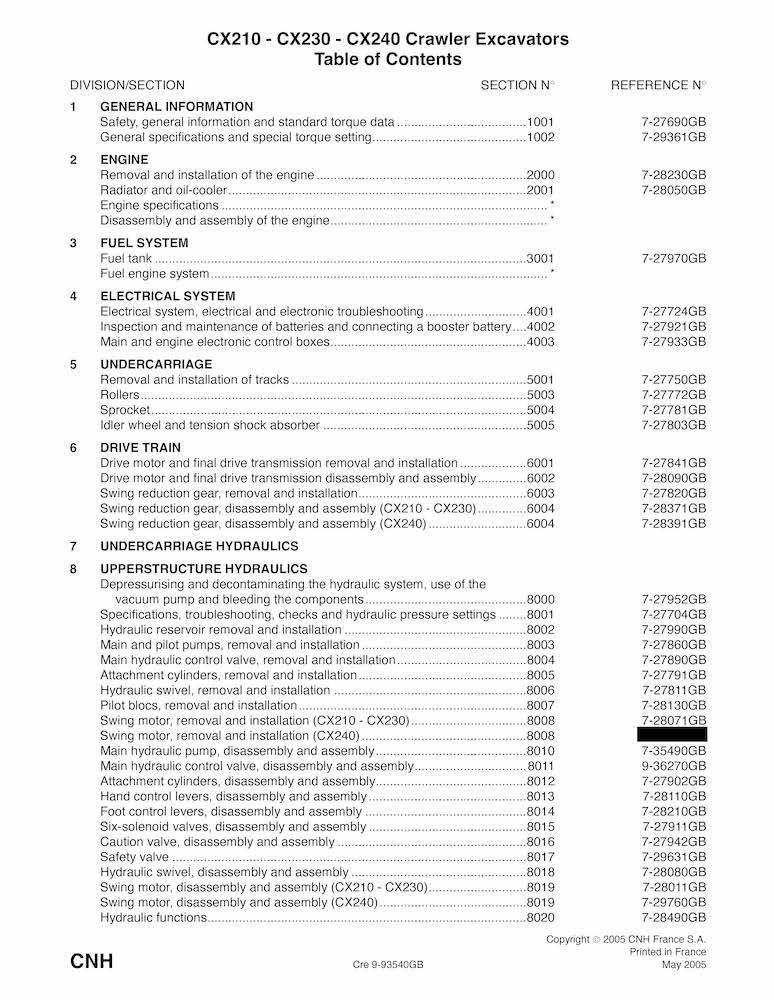
Case CX210, CX230, CX240 excavator pdf service manual
CASE-9-93610-SM
$45.90
No tax
Format: PDF
Pages: 648
File size: 70.59 MB
Language: English
Models: CX210, CX230, CX240
Create an account and join to our cumulative discounts program. Spend at least $29.9 and get 10.00% discount.
Rating:
(0)
Table of Contents for CASE-9-93610-SM-EN manual
- CX210 CX230 CX240 Crawler Excavators Table of Contents
- SAFETY, GENERAL INFORMATION AND TORQUE SPECIFICATIONS
- TABLE OF CONTENTS
- GENERAL INFORMATION Cleanning
- Gears
- Oil seals, O-rings and gaskets
- Shafts
- Inspection
- Service parts
- Bearings
- Lubrication
- Needle bearings
- SAFETY
- STANDARD TORQUE DATA FOR CAP SCREWS AND NUTS Tightening of cap screws, nuts
- Torque table
- GENERAL SPECIFICATIONS AND SPECIAL TORQUE SETTINGS
- TABLE OF CONTENTS
- TYPE, SERIAL NUMBER AND YEAR OF MANUFACTURE OF THE MACHINE
- Machine
- Engine
- Component serial numbers
- FLUIDS AND LUBRICANTS
- Grease
- Hydraulic fluid
- Transmission component oil
- Engine oil
- Oil viscosity/Oil range
- Environment
- Fuel
- Components made from plastic or resin
- Anti-freeze/Anti-corrosion
- SPECIFICATIONS Engine
- Capacities
- Electrical system
- Hydraulic system
- Cylinder
- Control valve
- Swing
- Travel
- Undercarriage
- Attachment
- Weight of components
- DIMENSIONS AND LIMIT OF WEAR AND TEAR OF THE TRACKS SET Toothed wheel
- Idler wheel
- Upper roller
- Lower roller
- Track
- DIMENSIONS AND LIMIT OF WEAR AND TEAR OF THE MOBILE JOINTS OF THE ATTACHMENT
- 1. Boom foot/Undercarriage
- 2. Boom cylinder foot/Undercarriage
- 3. Boom cylinder head/Boom
- 4. Dipper cylinder foot/Boom
- 5. Boom/Dipper
- 6. Dipper cylinder head/Dipper
- 7. Bucket cylinder foot/Dipper
- 8. Connecting rod/Dipper
- 9. Compensator/Bucket
- 10. Connecting rod/Compensator/Bucket cylinder head
- 11. Dipper/Bucket
- SPECIAL TORQUE SETTINGS
- MACHINE OVERALL DIMENSIONS
- REMOVAL AND INSTALLATION OF THE ENGINE
- TABLE OF CONTENTS
- SPECIFICATIONS
- SPECIAL TORQUE SETTINGS
- ENGINE Removal and installation
- RADIATOR AND OIL-COOLER
- TABLE OF CONTENTS
- SPECIFICATIONS
- RADIATOR AND OIL-COOLER
- Removing the oil-cooler
- Installing the oil-cooler
- Removing the radiator
- Installing the radiator
- CHANGING THE RADIATOR OR THE OIL-COOLER Disassembly and assembly
- REMOVAL AND INSTALLATION OF THE FUEL RESERVOIR
- TABLE OF CONTENTS
- SPECIFICATIONS
- FUEL RESERVOIR Removal
- Installation
- Description
- ELECTRICAL AND ELECTRONIC CIRCUIT AND TROUBLESHOOTING
- TABLE OF CONTENTS
- SPECIFICATIONS
- SPECIAL TOOLS
- LOCATION OF COMPONENTS General location of the components (outside the cab)
- General location of the components (outside the cab)
- Relay and main fuses (battery compartment)
- General location of the components (inside the cab)
- Fuse box
- Instrument panel
- OPERATING PRINCIPLES Engine checks
- Work mode selection
- H/S/L mode checking
- Auto mode checking
- Acceleration checking
- Engine idle checking (automatic/manual)
- Breaker mode checking
- Automatic engine preheat
- Auto engine warm-up
- Idle checking using the battery voltage and the coolant temperature
- Engine emergency stop
- Back-up mode
- Function locking
- Power boost
- Swing brake
- Travel mode
- Supply cut-off delayed
- Protection by power transistor
- Coolant temperature indicator
- Hydraulic oil temperature indicator
- Fuel level
- Engine fuel injection pump electronic regulator
- ACCESS AND CONTENTS OF MONITOR DISPLAYS (Diagnostic mode) Access to monitor displays
- Machine condition
- Diagnostic code
- Machine history
- Re-initialisation
- WARNING MESSAGES Message display
- EXCAVATOR MODEL SELECTION PROCEDURE
- Changing the language code
- CHANGING THE ACCESS CODE FOR THE ANTI-THEFT SYSTEM
- TROUBLESHOOTING Prior inspections
- Reading the organisation charts
- Procedures
- Low fuel
- Add coolant solution
- Low engine oil pressure
- Overheating
- Defective battery charge circuit
- Electrical system troubleshooting
- Travel
- ELECTRICAL INSPECTION OF COMPONENTS Inspection equipment
- Proportional solenoid
- 6 solenoid valve block
- Engine emergency stop motor
- Engine rpm sensor
- Engine coolant and hydraulic oil temperature sensor
- Pressure sensor
- INSPECTION AND MAINTENANCE OF BATTERIES AND CONNECTING A BOOSTER BATTERY
- TABLE OF CONTENTS
- SAFETY INSTRUCTIONS SPECIFICATIONS
- MAINTENANCE Electrolyte level
- Inspecting and cleaning the battery
- INSPECTING THE BATTERY
- Visual checks
- Checking the specific gravity
- Charge test
- CHARGING THE BATTERY
- BATTERY CHARGING GUIDE
- PREPARING A DRY CHARGED BATTERY FOR USE
- CONNECTING A BOOSTER BATTERY
- MAIN ELECTRONIC CONTROL BOX ENGINE ELECTRONIC CONTROL BOX
- TABLE OF CONTENTS
- MAIN ELECTRONIC CONTROL BOX AND ENGINE ELECTRONIC CONTROL BOX Removal
- Main electronic control box
- Engine electronic control box
- Installation
- REMOVAL AND INSTALLATION OF THE TRACKS SET
- TABLE OF CONTENTS
- SPECIFICATIONS
- SPECIAL TORQUE SETTINGS
- SPECIAL TOOLS
- TRACKS SET Description
- Removal
- Installation
- Track tension adjustment
- Checking pin and bushing wear
- UPPER AND LOWER ROLLERS
- TABLE OF CONTENTS
- SPECIFICATIONS
- SPECIAL TORQUE SETTINGS
- SPECIAL TOOLS
- LOWER ROLLER Description
- Removal
- Reconditioning
- Disassembly
- Assembly
- Inspection
- Installation
- UPPER ROLLER Description
- Removal
- Reconditioning
- Disassembly
- Inspection
- Assembly
- Installation
- CHECKING FOR LEAKS
- SPROCKET
- TABLE OF CONTENTS
- SPECIFICATIONS
- SPECIAL TORQUE SETTINGS
- SPROCKET Removal
- Installation
- IDLER WHEEL AND TENSION SHOCK ABSORBER
- TABLE OF CONTENTS
- SPECIFICATIONS
- SPECIAL TORQUE SETTINGS
- SPECIAL TOOLS
- REMOVAL AND INSTALLATION OF THE IDLER WHEEL AND THE TENSION SHOCK ABSORBER Removal
- Installation
- DISASSEMBLY AND ASSEMBLY OF THE IDLER WHEEL Description
- Reconditioning
- Disassembly
- Inspection
- Assembly
- Leakage test
- DISASSEMBLY AND ASSEMBLY OF THE TENSION SHOCK ABSORBER Description
- Assembly
- Disassembly
- TRACK TENSION CYLINDER (CX130, CX160, CX230 AND CX240) Description
- Removal
- Disassembly
- Assembly
- Inspection
- Installation
- TRACK TENSION CYLINDER (CX180/CX210) Description
- Removal
- Disassembly
- Inspection
- Assembly
- Installation
- DRIVE MOTOR AND FINAL DRIVE TRANSMISSION REMOVAL AND INSTALLATION
- TABLE OF CONTENTS
- SPECIFICATIONS
- SPECIAL TORQUES
- DRIVE MOTOR AND FINAL DRIVE TRANSMISSION Removal and installation
- NOTES
- DISASSEMBLY AND ASSEMBLY OF THE TRAVEL MOTOR/REDUCTION GEAR ASSEMBLY
- TABLE OF CONTENTS
- SPECIFICATIONS
- SPECIAL TORQUE SETTINGS
- INTERCHANGEABLE PRODUCTS
- TRAVEL MOTOR/REDUCTION GEAR ASSEMBLY
- HYDRAULIC MOTOR
- REMOVAL AND INSTALLATION OF THE SWING REDUCTION GEAR
- TABLE OF CONTENTS
- SPECIFICATIONS
- SPECIAL TORQUE SETTINGS
- TOOLS REQUIRED
- SWING REDUCTION GEAR Removal
- Installation
- SWING REDUCTION GEAR CX210 CX230
- TABLE OF CONTENTS
- SPECIFICATIONS
- SPECIAL TORQUE SETTINGS
- SWING REDUCTION GEAR Description
- Disassembly
- Assembly
- SWING REDUCTION GEAR CX240
- TABLE OF CONTENTS
- SPECIFICATIONS
- SPECIAL TORQUE SETTINGS
- SWING REDUCTION GEAR Description
- Disassembly
- Assembly
- DEPRESSURISING AND DECONTAMINATING THE HYDRAULIC SYSTEM, USE OF THE VACUUM PUMP AND BLEEDING THE COMPONENTS
- TABLE OF CONTENTS
- SPECIAL TOOLS
- RELEASING PRESSURE IN THE HYDRAULIC SYSTEM
- BLEEDING AIR FROM THE MAIN HYDRAULIC SYSTEM COMPONENTS
- Attachment cylinders
- Hydraulic pump
- Hydraulic swing motor
- VACUUM PUMP Installation
- Removal
- CLEANING THE HYDRAULIC SYSTEM General
- Types of contamination
- Decontamination of the hydraulic system
- SPECIFICATIONS, TROUBLESHOOTING, CHECKS AND HYDRAULIC PRESSURE SETTINGS
- TABLE OF CONTENTS
- SPECIFICATIONS
- SPECIAL TOOLS Tester
- IDENTIFICATION OF HYDRAULIC COMPONENTS Pump CX130/CX160 (Uchida)
- Pump CX130/CX160/CX180/CX210/CX230/CX240 (Kawasaki)
- Control valve CX130/CX160/CX180
- Control valve CX210/CX230/CX240
- 6 solenoid valve manifold
- PREPARATION BEFORE INSPECTION Releasing pressure in the hydraulic system
- Installing the flowmeter
- Installing the pilot pressure test point
- Display on diagnostic screen "CHK1"
- Warming up the engine
- Warming up the hydraulic fluid
- CHECKING AND PRESSURE SETTING PROCEDURE
- Checking the pilot accumulator
- Pilot system secondary relief valve (H)
- Main relief valve (A)
- Secondary control valve attachment relief valves (B, C, D, E, F and G)
- Secondary relief valves of the boom safety valves (B1 and B2)
- Dipper secondary relief valve (D1)
- Swing secondary relief valves (I, J)
- Checking the swing braking pressure
- Travel secondary relief valve (K, L)
- Checking the pressure delivered by the proportional valve
- Checking for leaks on the travel motor
- By-pass travel checking
- Checking the swing motor for leaks
- TROUBLESHOOTING Travel drift
- Not possible to select 2nd travel speed
- No swing or slow swing
- With the excavator on a slope, the swing brake does not hold
- No movement on any function
- Lack of power or speed on one of the attachment movements
- Not possible to select hard/soft shock absorbing system The boom or the dipper does not lower
- REMOVAL AND INSTALLATION OF THE HYDRAULIC RESERVOIR
- TABLE OF CONTENTS
- SPECIFICATIONS
- HYDRAULIC RESERVOIR Removal
- Installation
- Description
- REMOVAL AND INSTALLATION OF THE MAIN HYDRAULIC PUMP AND THE PILOT PUMP
- TABLE OF CONTENTS
- SPECIFICATIONS
- SPECIAL TORQUE SETTINGS
- MAIN HYDRAULIC PUMP Removal and installation
- PILOT PUMP Removal and installation
- HYDRAULIC PUMP COUPLING Description
- Removal and installation
- REMOVAL AND INSTALLATION OF THE MAIN HYDRAULIC CONTROL VALVE
- TABLE OF CONTENTS
- SPECIFICATIONS
- SPECIAL TORQUE SETTINGS
- MAIN HYDRAULIC CONTROL VALVE Removal and installation
- REMOVAL AND INSTALLATION OF THE ATTACHMENT CYLINDERS
- TABLE OF CONTENTS
- SPECIFICATIONS
- PREPARATION BEFORE REMOVAL/INSTALLATION
- BOOM CYLINDER Description
- Removal
- Installation
- DIPPER CYLINDER Description
- Removal
- Installation
- BUCKET CYLINDER Description
- Removal
- Installation
- REMOVAL AND INSTALLATION OF THE HYDRAULIC SWIVEL
- TABLE OF CONTENTS
- SPECIFICATIONS
- SPECIAL TORQUE SETTINGS
- HYDRAULIC SWIVEL Removal and installation
- REMOVAL AND INSTALLATION OF THE PILOT FUNCTION BLOCKS
- TABLE OF CONTENTS
- SPECIAL TORQUE SETTINGS
- PILOT FUNCTION BLOCKS Travel pedal block
- LH control lever
- RH control lever
- Swing shuttle block
- Cushion control valve
- Servo control and return manifold block
- 6 solenoid valve block
- REMOVAL AND INSTALLATION OF THE SWING MOTOR CX210 CX230
- TABLE OF CONTENTS
- SPECIFICATIONS
- SPECIAL TORQUE SETTINGS
- SWING MOTOR Removal and installation
- MAIN HYDRAULIC PUMP
- TABLE OF CONTENTS
- SPECIFICATIONS
- SPECIAL TORQUE SETTINGS
- WEAR INSPECTION
- IDENTIFYING THE COMPONENTS
- Description
- DISASSEMBLY
- ASSEMBLY
- REMOVAL AND INSTALLATION OF THE CONTROL VALVE
- TABLE OF CONTENTS
- SPECIFICATIONS
- TOOLS REQUIRED
- SPECIAL TORQUE SETTINGS
- CONTROL VALVE Description
- Identifying the ports
- Disassembly
- General instructions
- Separating the sections
- Load holding block
- Precautions before assembly
- Assembly
- Cleaning
- Inspection
- DISASSEMBLY AND ASSEMBLY OF THE ATTACHMENT CYLINDERS
- TABLE OF CONTENTS
- SPECIFICATIONS
- SPECIAL TORQUE SETTINGS
- SPECIAL TOOLS
- CYLINDERS Boom cylinder description
- Dipper cylinder description
- Bucket cylinder description
- Disassembly
- Inspection
- Assembly
- DISASSEMBLY AND ASSEMBLY OF THE CONTROL LEVERS
- TABLE OF CONTENTS
- SPECIFICATIONS
- CONTROL LEVER Description
- Disassembly
- Inspection
- Assembly
- DISASSEMBLY AND ASSEMBLY OF THE CONTROL PEDALS
- TABLE OF CONTENTS
- SPECIFICATIONS
- TORQUE SETTING
- SPECIAL TOOLS
- CONTROL PEDAL
- DISASSEMBLY AND ASSEMBLY OF THE SIX SOLENOID VALVES BLOCK
- TABLE OF CONTENTS
- SIX SOLENOID VALVES BLOCK Identifying the ports and the solenoid valves
- Section
- Disassembly and assembly
- Inspection
- DISASSEMBLY AND ASSEMBLY OF THE CUSHION CONTROL VALVE
- TABLE OF CONTENTS
- CUSHION CONTROL VALVE Description
- Disassembly
- Assembly
- Inspection
- HOSE BURST CHECK VALVE
- TABLE OF CONTENTS
- TORQUE SETTINGS
- BOOM RELIEF VALVE Marking the ports
- Installation
- Removal
- Disassembly
- Assembly
- ARM RELIEF VALVE Marking the ports
- Installation
- Removal
- Disassembly
- Assembly
- DISASSEMBLY AND ASSEMBLY OF THE HYDRAULIC SWIVEL
- TABLE OF CONTENTS
- SPECIAL TORQUE SETTINGS
- HYDRAULIC SWIVEL
- DISASSEMBLY AND ASSEMBLY OF THE HYDRAULIC SWING MOTOR
- TABLE OF CONTENTS
- SPECIFICATIONS
- TORQUE SETTINGS
- HYDRAULIC SWING MOTOR Description
- Disassembly
- Inspection
- Assembly
- RELIEF VALVE Disassembly
- Inspection
- Assembly
- DISASSEMBLY AND ASSEMBLY OF THE SWING HYDRAULIC MOTOR
- TABLE OF CONTENTS
- SPECIFICATIONS
- SPECIAL TORQUE SETTINGS
- TOOL TO BE MANUFACTURED
- HYDRAULIC SWING MOTOR Description
- Disassembly
- Inspection
- Wear limit
- Assembly
- HYDRAULIC FUNCTIONS
- TABLE OF CONTENTS
- HYDRAULIC FUNCTIONS Function List
- Controls in Neutral
- High Speed Travel Circuit
- Low Speed Travel Circuit
- Straight Line Travel Circuit
- Swing Circuit
- Variable Priority Valve Circuit
- Boom Raising Circuit
- Boom Lowering Circuit, Load Holding Valve
- Boom Lowering Reinjection Circuit
- Boom Lowering Anti-vibration Circuit
- Dipper Extending Circuit
- Dipper Retracting Circuit
- Dipper Retracting Reinjection Circuit
- Bucket Opening Circuit
- Bucket Closing Circuit
- Crusher Circuit
- Breaker Circuit
- NOTES
- QUICK COUPLER
- TABLE OF CONTENTS
- IDENTIFICATION OF COMPONENTS Description
- QUICK COUPLER Removal
- Inspection
- Hook and cylinder removal
- UPPERSTRUCTURE, TURNTABLE AND COUNTERWEIGHT
- TABLE OF CONTENTS
- SPECIAL TORQUE SETTINGS
- SPECIFICATIONS
- UPPERSTRUCTURE Inspection
- Removal
- Installation
- COUNTERWEIGHT Description
- Removal
- Installation
- BOOM, DIPPER AND BUCKET
- TABLE OF CONTENTS
- SPECIFICATIONS
- BUCKET Description
- Removal
- Installation
- Shimming the bucket
- DIPPER Description
- Removal
- Installation
- BOOM Description
- Removal
- Installation
- SEAT AND SAFETY BELT
- TABLE OF CONTENTS
- SPECIFICATIONS
- OPERATOR'S SEAT Description
- Removal
- Installation
- SAFETY BELT Removal
- Installation
- CAB AND CAB EQUIPMENT
- TABLE OF CONTENTS
- SPECIFICATIONS
- SPECIAL TORQUE SETTINGS
- CAB Removal
- Installation
- HEATING BLOCK/AIR-CONDITIONING BLOCK Description
- Removal
- Installation
- WINDSHIELD WIPER MOTOR Description
- Removal
- Installation
- AIR CONDITIONER TROUBLESHOOTING AND SYSTEM CHECKS
- TABLE OF CONTENTS
- SAFETY PROCEDURES
- SPECIAL TOOLS
- OPERATION
- REFRIGERANT SCHEMATIC
- ELECTRICAL SCHEMATIC
- PRE-STUDIES The Blow is not cool
- The speed of blower motor is not changeable
- Magnetic Clutch does not work
- Blow air is not changeable in fresh or recycle
- A/C Mode is not changeable
- TROUBLESHOOTING
- The Blow is not COOL
- TROUBLESHOOTING The Blow is not HOT
- TROUBLESHOOTING Blower Motor does not work
- TROUBLESHOOTING The speed of blower motor is not changeable
- Magnet Clutch does not work
- TROUBLESHOOTING
- Blow air is not changeable in fresh or recycle
- A/C mode is not changeable
- Troubleshooting for coolant circuit
- Language
- English
- Document type
- Service manual
- Machinery type
- excavator

High-Quality PDF Service Manuals for Professional Repair
Our Service Manuals are comprehensive digital products delivered in convenient PDF formats, providing the exact technical data required to maintain, repair, and troubleshoot your equipment. Whether you are a fleet owner or a professional technician, having a dedicated PDF service manual ensures you have instant access to factory-spec information.
What is Included in Our Service Manuals?
Every repair and service manual we provide is structured to offer a professional-grade approach to machinery maintenance. When you download a manual, you gain access to:
-
Detailed Technical Specifications: Precise clearances, capacities, and settings.
-
Step-by-Step Procedures: Guided instructions for assembly, disassembly, and component repair.
-
High-Resolution Diagrams: Clear schematics and exploded views for easy parts identification.
-
Diagnostic Flowcharts: Logic-based troubleshooting to identify faults quickly.
-
Safety & Compliance Guidelines: Essential precautions to ensure safe operation and regulatory compliance.
Why Choose a Digital PDF Service Manual?
A Service Manual is more than just a book; it is an essential tool for maximizing the lifetime of complex machinery. By using our digital service manuals, technicians can accurately diagnose problems, perform precision repairs, and reduce costly downtime.
Unlike paper alternatives, our PDF manuals are searchable, allow for high-quality zooming on intricate diagrams, and can be accessed on any device—from the workshop floor to the field.
Tap to zoom