Fendt is a German manufacturer of agricultural tractors and machines, manufacturing and marketing a full line of tractors, combine harvesters and balers. It is part of the AGCO Corporation. It was founded in 1930 by Xaver Fendt and purchased by AGCO in 1997.
History
The history of the craftsman family Fendt goes back 350 years. The production of tower clocks, lead strings and violins spread their fame in the Allgäu region. The family also farmed on a sideline and had a small trade in agricultural equipment. Johann Georg Fendt, born on 16 August 1868, took over the family business of his father Franz Xaver in 1898 and began selling Deutz stationary engines, where he also carried out on-site maintenance and repair work. While the first born son Xaver left the family business and worked at big companies like Deutz or BMW. Hermann also worked with his father in his daily work. Both recognized the need for agricultural utility machines and ventured in 1928 to build a motorized grass mower.
Fendt Favorit 3 produced in 1960's
The first 6 hp Dieselross tractor was built in 1930 by the brothers Hermann (1911-1995) and Xaver Fendt (1907-1989) under the guidance of their father Johann Georg Fendt (1868-1933). In 1937, the two incorporated the company in the commercial register. In 1938, the Fendt brothers built the Dieselross F 22 with up to 22 hp which was followed by Dieselross series until 1958. This development made them known beyond the borders of the Allgäu for the first time. In 1958, a new class of tractor series "ff" series with the types Favorit, Farmer and Fix were launched. The design was changed, and offered the engine power from 15 to 80 hp. The favorite 1 was trend-setting in form and technical equipment, with multi-course fine-step transmission system. The recent series of Vario Class was unveiled in 1996 which are innovative in design, revolutionary in gearbox technology and the world's first large tractor with the stepless Vario transmission.
Fendt is considered a premium brand within the AGCO Group and, with a development budget of around € 62 million in 2013, is a global driver of innovation in the agricultural equipment industry. The product range includes tractors, forage harvesters, combine harvesters, rakes, tedders, mowers and balers.
The Fendt brand has the largest share in the tractor market of Europe. Fendt is the market leader in Germany with a share of 24.2 percent in 2018. With a total number of 17,837 tractors were sold alone in France, which until then the highest number in the company's history. In the annual image barometer published by the DLG, in which German contractors and farmers are surveyed about agricultural engineering companies, Fendt took first place in 2013 with 99.3 out of a possible 100 points.[3] The company is a member of the VDMA , Department of Agricultural Engineering.
Product Range
Tractors
Fendt 1000 Vario with a Horsch cultivator
200 Vario Series 51–81 / 70–110
300 Vario Series 70–92 / 95–135
500 Vario Series 92–121 / 125–165
700 Vario Series 96–132 / 130–240
800 Vario Series 136–151 / 185–287
900 Vario Series 202–265 /275 –390
1000 Vario Series 279–368 / 380–517
Combines
Fendt Ideal 9T
IDEAL 336 kW / 451 hp /589 kW / 790 hp
C-Series 225 kW / 306 hp / 265 kW / 360 hp
L-Series 179kW / 243 hp / 225kW / 306 hp
E-Series 5225 160 kW / 218 hp
E-Series 5185 129 kW / 175 hp
Balers
990 80 cm x 90 cm
1270 120 cm x 70 cm
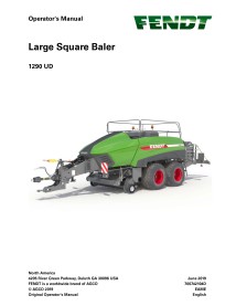
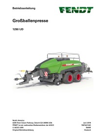
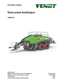
1290 120 cm x 90 cm
1290 XD 120 cm x 90 cm
12130 120 cm x 130 cm
Forage Harvesters
Fendt Katana 85
Fendt Katana Power (KW/hp)
65 460 kW / 625 hp
85 625 kW / 900 hp
Fendt Plant protection technology[edit]
Fendt Rogator Power (KW/hp) Nominal capacity (l) Boom widths (m)
600 125-167 kW / 170-227 hp 3850 - 6000 24 - 36
300 - 3500 - 6930 24 - 30
Miscellaneous
Fendt Cargo Loaders (for tractors)
Fendt Variotronic (electronic terminal for tractors/combine harvesters)
Fendt ISU Range (industrial tractors)