Liebherr A900, A902, A912, A922, A942 hydraulic excavator pdf service manual
Format: PDF
Pages: 1264
File size: 66.91 MB
Language: English
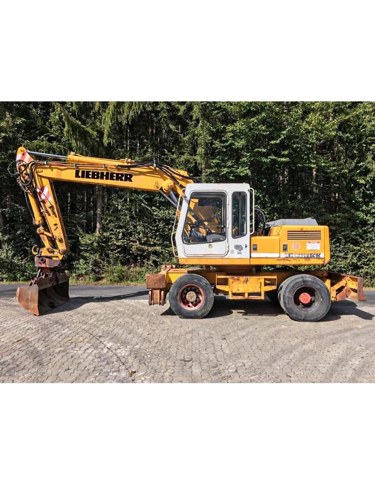
Models: A 900, A 902, A 912, A 922, A 942
Service manual for Liebherr A900, A902, A912, A922, A942 hydraulic excavator is available for instant download after purchase at any time. It can be downloaded and viewed on any device. Download free preview PDF file using the link in Attachments TAB
Table of Contents for LIEBHERR-A900-A942-EN manual
- Book I A 900 - A 942
- Titel
- Introduction
- Index
- 1.2 Tables / Data / Torque
- 1.2.00 Description of metric bolts / Wrench sizes
- 1.2.01 Tightening torques bolts grade 8.8
- 1.2.02 Tightening torques bolts grade 10.9
- 1.2.03 Tightening torques bolts grade 12.9
- 1.2 05 Tightening torques for Durlock bolts grade 12.9
- 1.2.08 1.2.01 Tightening torques for Ermeto connections
- 1.2.10 Hole diameters for tapping standard metric thread
- 1.2.11 Hole diameters for tapping fine metric thread
- 1.2.15 ISO - Tolerances
- 1.2.20 Graphic sysmbols for hydraulic and pneumatic schematics
- 1.2.25 Graphic symbols for electrical diagrams
- 1.3 Tools / Special tools
- 1.3.00 Special tools for excavator
- 1.3.01 Mini text system
- 1.3.02 Pressure gauge
- 1.3.03 Flow meter
- 1.3.04 Test fitting
- 1.3.05 Spool clamp
- 1.3.06 Leakag plate
- 1.3.07 Spool travel measuring tool
- 1.3.08 Mounting tool for hydraulic cylinder, pumps and variable flow motors
- 1.3.09 Piston wrench
- 1.3.10 Piston nut wrench
- 1.3.12 Piston nut wrench
- 1.3.13 Test fitting for variable flow motors LMV
- 1.3.14 Removing device for transmital travel gear
- 1.4 Welding
- 1.4.01 Welding joints (Din 912)
- 1.5 Lubricants
- 1.5.01 Lubricant chart
- 1.5.02 Lubricating oil
- 2.0 Technical data / Inspection schedule
- 2.0.01 Technical data A 900
- 2.0.02 Technical data A 902
- 2.0.04 Technical data A 912
- 2.0.06 Technical data A 922
- 2.0.09 Technical data A 942
- 2.0.20 Inspection schedule A 900
- 2.0.22 Inspection schedule A 902
- 2.0.24 Inspection schedule A 912
- 2.0.26 Inspection schedule A 922
- 2.0.29 Inspection schedule A 942
- 2.1 Engine
- 2.1.01 Deutz Engine FL 912
- 2.1.02 Deutz Engine BFL 913/913 C
- 2.1.03 Deutz Engine FL 912
- 2.1.05 Liebherr Engine D 904 NA / D 904 T
- 2.1.06 Liebherr Engine D 906 NA / D 906 T
- 2.1.10 Sensor controlled low idle automatic
- 2.1.11 Sensor controlled low idle automaic
- 2.2 Swing gear / Swing brake
- 2.2.00 Torque value
- 2.2.02 Remove and install swing gear A 900 / A/R 902 - 912
- 2.2.03 Remove and install swing gear A/R 922 / R 932 / A/R 942
- 2.2.05 Disassembly / Assembly Instructions A 900 / A/R 902 - 912
- 2.2.06 Disassembly / Assembly Instructions A/R 922 / R 932 / A/R 942
- 2.2.10 Swing brake / Maintenance and pressure settings
- 2.2.11 Swing brake / Remove and install
- 2.2.12 Swing brake / Funktion and operating / Bleed brake system
- 2.2.13 Repair and funktion od wheel cylinder with brake assembly
- 2.2.14 Repair and funktion of master cylinder
- 2.2.15 Swing brake troobleshooting
- 2.3 Hydraulic system
- 2.3.00 General information
- 2.3.01 Hydraulic system Pressure settings
- 2.3.05 Hydraulic system A 900
- 2.3.06 Hydraulic system A 902
- 2.3.07 Hydraulic system A 912 / A 922
- 2.3.08 Hydraulic system A 942
- 2.3.20 Pressure cut in / Lift
- 2.3.25 Front / Rear outriggers
- 2.3.30 Hydraulic servo system
- 2.3.32 Servo control with joystick
- 2.3.33 Servo control with foot pedal
- 2.3.40 Control valves
- 2.3.42 Control valves NG 16 / NG 22
- 2.3.50 Pressure relief valve - Direct acting
- 2.3.51 Pressure relief valve - Pilot operated
- 2.3.52 Pressure relief valve - Direct acting
- 2.3.53 Two way pressure relief valve
- 2.3.54 Suction valve
- 2.3.55 Thermostat valve
- 2.3.56 Flow divider
- 2.3.57 Restrictor check valve
- 2.3.58 Check valve with hydraulic release
- 2.3.59 Travel brake valve
- 2.3.62 Pressure relief valve with pressure cut in
- 2.3.80 Hydraulic pump A8V (Hydromatik) A 900 - A 902
- 2.3.81 Hydraulic pump A8V (Hydromatik) A 912 - A 932
- 2.3.84 Hydraulic pump LPVD (Liebherr) A 900 - A 942
- 2.3.88 Comparative flow test
- 2.3.89 Pump flow diagram
- 2.3.91 Hydraulic variable flow motor A6V (Hydromatik) A 900 - A 942
- 2.3.92 Hydraulic fixed displacement motor LMF (Liebherr) A 900 - A 942
- 2.3.96 Hydraulic variable flow motor LMF (Liebherr) A 902 - A 922
- 2.4 Air pressure system
- 2.4.01 Pressure chart
- 2.4.05 Description and fiunction A 900
- 2.4.06 Description and function A 902 / A 912 / A 922
- 2.4.20 Description and function of components
- 2.5 Rotary connection
- 2.5.02 Five-way air rotary connection
- 2.5.05 Oil rotary connection "Grau"
- 2.5.06 Oil rotary connection "Sigma"
- 2.5.08 Oil rotary connection "Liebherr"
- 2.6 Electrical system
- 2.6.01 General notes
- 2.6.02 Battery handling and maintenance
- 2.6.03 Starter
- 2.6.04 Alternator
- 2.6.05 Glow plug
- 2.6.08 Electrical system A 900
- 2.6.10 Electrical system A 902 - A 922
- 2.6.15 Electrical system A 902 - A 922
- 2.7 Heater / Air conditioner
- 2.7.05 Engin oil heater
- 2.7.08 Cab heater installation A/ R 900
- 2.7.08 Cab heater installation A 902 - A 922
- 2.7.09 Cab heater installation A 942
- 2.7.10 Cab heater D1L
- 3.1 Two speed gear box
- 3.1.03 Remove and install / Gearbox
- 3.1.05 Diassembly and assembly / Two speed gear box
- 3.2 Front and real axle / Differential
- 3.2.01 Examples of Gleason gear
- 3.2.03 Removing and installation of front axle and differential
- 3.2.04 Removing and installation of rear axle and differential
- 3.2.05 Diassembly and assembly of differential - Carrier A1
- 3.2.06 Diassembly and assembly of differential - Carrier B
- 3.2.07 Diassembly and assembly of differential - Carrier C
- 3.2.10 Removing and installing / Front Axle
- 3.2.11 Removing and installing / Front axle
- 3.2.15 Removing and installing / Rear axle
- 3.3 Hydrostatic steering
- 3.3.01 Hydrostatic steering
- 3.3.05 Servostat
- 3.3.06 Flow indicator
- 3.4 Oscillating axle support
- 3.4.05 Oscillating axle support A 900 / A 942
- 3.4.06 Oscillating axle suppert A 902 - A 922
- 3.5 Brakes
- 3.5.01 Pressure chart and instructions
- 3.5.02 Removing and installing - Four wheel brake
- 3.5.03 Construction and funktion of brakes / Bleeding
- 3.5.04 Function and adjusting - Hydraulic simplex brake
- 3.5.05 Function and repair of master cylinder
- 3.5.06 Troubleshooting
- 3.5.10 Function and instructions of brake (Pneumatic)
- 3.5.11 Function and adjusting of brake (Mechanical)
- 3.5.12 Troubleshooting
- 3.6 Swing ring
- 3.6 Remove and install swing ring
- 5.2 Special equipment / accessory kits
- 5.2.02 Overload warning device / General data
- 5.2.03 Overload warning device A 900
- 5.2.04 Overload warning device A/ R 902 - A/R 922
- 5.2.05 Overload warning device A 902 - A 922
- 5.2.06 Overload warning device A/R 942
- 5.2.09 Hoist limit
- 5.2.10 Load check valve
- 5.2.11 Load check valve / Leckoil free
- 5.2.12 Atrachment AS1 A/R 900 -902
- 5.2.13 Attachment AS1 A/R 912 - R 932
- 5.2.14 Attachment AS1 A/R 942
- 5.2.15 Attachment for elevated cab A 912 - A 922
- 5.2.16 Attachment for elevated cab A 902 - A 922
- 5.2.18 Attachment ASH A/R 900
- 5.2.19 Attachment ASH A/R 900 - R 932
- 5.2.20 Attachment ASH A 942
- 5.2.22 Attachment AHS1 A/R 902 - R 932
- 5.2.24 Attachment AHS2 A/R 892 - A 922
- 5.2.26 Attachment AHS3 A/R 902 - A 922
- 5.2.30 Grapple Attachment
- 5.2.31 Grapple rotary device
- 5.2.32 Quick change coupling
- 5.2.34 Pin lock
- 5.2.35 Limit switch for industrial attachment
- 5.2.36 Crane attachment
- 5.2.38 Industrial crane
- 5.2.40 Adjustable cab
- 5.2.42 Dumping attachment
- 5.2.44 Dozer blade
- 5.2.46 Outrigger control
- 5.2.47 Slipring rotary connenction
- 5.2.50 Hydraulic hammer
- 5.2.51 Special attachment
- 5.3 Hydraulic cylinder
- 5.3.01 Hydraulic cylinder - Torque values
- 5.3.02 Hydraulic cylinder - Removing and installing
- 5.3.05 Hydraulic cylinder without cushioning
- 5.3.10 Hydraulic cylinder without/with cushioning
- 5.3.15 Hydraulic cylinder - Steering
- 5.3.21 Hydraulic cylinder A/R 902
- 5.3.22 Hydraulic cylinder A/R 912
- 5.3.23 Hydraulic cylinder A/R 922
- 5.3.25 Hydraulic cylinder A/R 942
High-Quality PDF Service Manuals for Professional Repair
Our Service Manuals are comprehensive digital products delivered in convenient PDF formats, providing the exact technical data required to maintain, repair, and troubleshoot your equipment. Whether you are a fleet owner or a professional technician, having a dedicated PDF service manual ensures you have instant access to factory-spec information.
What is Included in Our Service Manuals?
Every repair and service manual we provide is structured to offer a professional-grade approach to machinery maintenance. When you download a manual, you gain access to:
-
Detailed Technical Specifications: Precise clearances, capacities, and settings.
-
Step-by-Step Procedures: Guided instructions for assembly, disassembly, and component repair.
-
High-Resolution Diagrams: Clear schematics and exploded views for easy parts identification.
-
Diagnostic Flowcharts: Logic-based troubleshooting to identify faults quickly.
-
Safety & Compliance Guidelines: Essential precautions to ensure safe operation and regulatory compliance.
Why Choose a Digital PDF Service Manual?
A Service Manual is more than just a book; it is an essential tool for maximizing the lifetime of complex machinery. By using our digital service manuals, technicians can accurately diagnose problems, perform precision repairs, and reduce costly downtime.
Unlike paper alternatives, our PDF manuals are searchable, allow for high-quality zooming on intricate diagrams, and can be accessed on any device—from the workshop floor to the field.