Shopping Cart
There are no more items in your cart
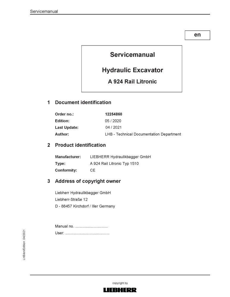
Liebherr A924 Rail Lytronic hydraulic excavator pdf service manual
LIEBHERR-A924_Rail
$45.90
No tax
Format: PDF
Pages: 1882
File size: 86.34 MB
Language: English
Models: A924 Rail Lytronic 1510
Service manual for A924 Rail Lytronic hydraulic excavator is available for instant download after purchase at any time. It can be downloaded and viewed on any device. Download free preview PDF file using the link in Attachments TAB
Create an account and join to our cumulative discounts program. Spend at least $29.9 and get 10.00% discount.
Rating:
(0)
Table of Contents for LIEBHERR-A924_Rail-EN manual
- Book I Chapter 010 - 200
- 000.002 Preface
- 010 Introduction
- 010.005 Standards and regulations
- 010.008 Component documentation
- 010.010 New features and changes
- 010.020 Safety instructions
- 010.043 Installation instructions: Mounting clamping nuts
- 010.050 Special tools, general
- 010.051 Special tools for hydraulic system
- 010.052 Special tools for electrical equipment
- 010.053 Special tools for diesel engine D924 A7-04
- 010.054 Special tools for slewing gearbox
- 010.056 Mounting device for multi-disc brake
- 010.058 Special tools for axles (ZF)
- 010.060 Special tools for two-way systems
- 010.070 Preservation guidelines
- 010.071 Conservation of hydraulic cylinders
- 010.072 Conservation guidelines for the SCR system
- 020 Technical data
- 020.001 Technical data
- 030 Maintenance
- 030.001 Maintenance
- 030.051 Adjustment checklist A924 Rail
- 030.100 Preparations
- 030.105 Machine-specific data
- 030.110 Diesel engine
- 030.115 Operating conditions
- 030.121 Servo control
- 030.125 Variable-displacement pump P1 and variable- displacement pump P2
- 030.130 Pump safety valve P1 and P2
- 030.135 Powertest
- 030.140 Control block, secondary pressures
- 030.145 Operating pressure, pressure cut-off P1 and P2
- 030.150 Slewing gear function
- 030.155 Hydraulic fan drive
- 030.160 Steering system
- 030.165 Brake system
- 030.170 Transmission
- 030.175 Tool Control high pressure circuit 1 and 2
- 030.220 Variable-displacement pump, rail guide system
- 030.225 Rail guide system
- 030.230 Rail wheel brake
- 030.235 Safety functions
- 030.240 Emergency hydraulics
- 030.245 Pneumatic wagon brake system
- 030.246 Hydraulic wagon brake system
- 040 Drive group
- 040.011 Technical data, diesel engine
- 040.021 Diesel engine D924 A7
- 040.022 Cummins QSB 4.5 diesel engine
- 040.026 SCR exhaust treatment system
- 040.027 Exhaust system (Cummins diesel engine)
- 040.031 Diesel exhaust fluid system
- 040.036 Fuel system
- 040.037 Engine fuel system (Cummins diesel engine)
- 040.041 Air filter system
- 040.042 Air filter system (Cummins diesel engine)
- 040.051 SCRF exhaust treatment system
- 040.060 Coupling
- 040.062 Cummins coupling
- 050 Cooling system
- 050.005 Coolant circuit
- 050.011 Cooling unit
- 050.020 Fan drive
- 050.030 Reversible fan drive
- 060 Working hydraulics
- 060.001 Overview of hydraulic symbols
- 060.002 Colour code of hydraulic schematics
- 060.003 Reducing pressure in hydraulic system
- 060.004 Bleeding hydraulic system
- 060.008 LSC system
- 060.020 Design of uppercarriage hydraulic system
- 060.032 Design of hydraulic system, undercarriage
- 060.050 Component list - hydraulic schematic
- 060.055 Components list, hydraulic schematic, undercarriage
- 070 Travel hydraulics
- 070.005 Travel hydraulics: overview
- 070.015 DMVA O 165 travel motor
- 080 Hydraulic components
- 080.010 PowerLift additional pressure stage
- 080.015 Hydraulic tank
- 080.025 Double variable-displacement pump DPVP O 108
- 080.040 Servo control unit
- 080.051 LSC control block
- 080.052 High-pressure circuit 1 (HDK1) control axis
- 080.053 Separating plate
- 080.054 Control axis / slewing gear
- 080.055 Medium pressure circuit control axis / turn grapple
- 080.056 Adjustable boom cylinder control axis
- 080.057 Pilot control valve 3x
- 080.058 Servo control valves
- 080.059 Check for leak oil at control valve blocks
- 080.070 Control block of rail guide system
- 080.072 Slewing gear motor
- 080.075 Rotary connection 13x
- 080.080 Hydraulic differential cylinder
- 080.090 Accumulator
- 080.100 Line break safety valve
- 080.105 Line break safety valve, stick cylinder
- 090 Steering system
- 090.010 Hydraulic steering system
- 100 Brake system
- 100.010 Hydraulic brake system with rail wheel brake
- 100.020 Compact brake block
- 100.025 Rail wheel brake
- 100.060 Pneumatic schematic of single-circuit wagon brake system
- 100.070 Pneumatic schematic of dual-circuit wagon brake system
- 100.080 Hydraulic schematic of dual-circuit wagon brake system
- 110 Electrical system
- 110.001 Overview of electrical symbols
- 110.002 Circuit diagrams in LIDOS
- 110.005 Overview of ground connections
- 110.011 Rail-road control unit
- 110.020 Electrical system: operator's platform, wheeled
- 110.030 Electrical system: uppercarriage
- 110.034 Electrical system: Fuses and relays
- 110.040 Electrical system: undercarriage
- 110.050 Electrical system, operator's platform
- 110.060 Circuit diagram: basic machine Cummins QSB
- 110.062 Circuit diagram: basic machine
- 110.080 Circuit diagram of D924 A7-04 diesel engine
- 110.084 Circuit diagram: diesel engine Cummins QSB
- 110.096 Resistance measurement
- 110.200 Pilot control unit / joystick
- 120 Travel gear mechanism
- 120.010 2 HL 270 / 290 transmission
- 120.022 Pilot control valve for transmission
- 130 Axles / rail guide system
- 130.001 Tyres
- 130.003 Checking oscillating axle bearing for wear
- 130.005 Oscillating axle support
- 130.020 Oscillating axle MS-E 3070
- 130.021 MT-E 3070 rigid axle
- 130.022 MS/MT-E 3070 input unit and differential
- 130.100 Rail guide axle: wear measurement
- 140 Steel parts - basic machine
- 140.010 Repair welding guideline
- 150 Working equipment
- 150.010 Dismantling and installing working attachment
- 150.015 Boom, adjustable in vertical/horizontal direction
- 150.040 Hydraulic quick coupler
- 150.042 Interface, third-party quick coupler
- 150.060 Electrical changeover between bucket and grapple operation
- 150.061 Manual changeover between bucket and grapple operation
- 150.062 Height limiting
- 150.064 Slew limitation
- 150.066 Load moment limitation
- 160 Cab / heating / air conditioning
- 160.021 Auxiliary heater
- 160.035 Heating and air conditioning unit
- 160.041 Air conditioning
- 160.045 Air conditioning diagnosis / service
- 170 Lubrication system
- 170.001 Repair of lubrication hose
- 170.005 Automatic central lubrication system
- 170.015 Central lubrication pump
- 170.025 Progressive distributor
- 180 Slewing gear mechanism / Slewing ring
- 180.020 Slewing gearbox
- 180.030 Slewing brake
- 180.032 Positioning slewing brake
- 180.050 Slewing ring
- 190 Equipment / Options
- 190.001 LiDAT remote diagnosis system
- 190.002 LiDAT: checking connection status
- 190.004 LiDAT remote diagnosis system (LiTU03)
- 190.005 LiDAT: creating a report and snapshot
- 190.007 Likufix coupling system
- 190.008 Check template for LIKUFIX
- 190.010 Tool control
- 190.014 Tool Management
- 190.022 Driver identification
- 190.040 Mower rake accessory kit
- 190.041 Tiltrotator TR-20/TR-25
- 190.053 Hydraulic connections on the stick
- 190.055 Bypass filter
- 190.060 Control unit pre-heating
- 190.062 Hydraulic oil pre-heating
- 190.064 Fuel pre-heating
- 190.066 Coolant pre-heating
- 190.068 Engine oil pre-heating
- 190.070 Backward stability
- 190.080 Trailer socket
- 190.090 Camera monitoring system
- 200 Diagnosis
- 200.005 Sculi variables editor
- 200.006 Sculi access to the variables
- 200.010 Testing and adjustment software wizard
- 200.012 Accelerating starting time from Sculi Wizard
- 200.035 CAN module addressing
- 200.090 Malfunctions
- 200.095 Information menu
- 200.100 Master 5: Reset to factory settings
- 200.102 Master 5: Connect "LiFT" function
- 200.104 Master 5: Software update
- 200.106 Master 5: Connect SCULi diagnostic software
- 200.108 Master 5: Service file
- 200.110 Master 5: Import license file
- Document type
- Service manual
- Language
- English
- Machinery type
- hydraulic excavator

High-Quality PDF Service Manuals for Professional Repair
Our Service Manuals are comprehensive digital products delivered in convenient PDF formats, providing the exact technical data required to maintain, repair, and troubleshoot your equipment. Whether you are a fleet owner or a professional technician, having a dedicated PDF service manual ensures you have instant access to factory-spec information.
What is Included in Our Service Manuals?
Every repair and service manual we provide is structured to offer a professional-grade approach to machinery maintenance. When you download a manual, you gain access to:
-
Detailed Technical Specifications: Precise clearances, capacities, and settings.
-
Step-by-Step Procedures: Guided instructions for assembly, disassembly, and component repair.
-
High-Resolution Diagrams: Clear schematics and exploded views for easy parts identification.
-
Diagnostic Flowcharts: Logic-based troubleshooting to identify faults quickly.
-
Safety & Compliance Guidelines: Essential precautions to ensure safe operation and regulatory compliance.
Why Choose a Digital PDF Service Manual?
A Service Manual is more than just a book; it is an essential tool for maximizing the lifetime of complex machinery. By using our digital service manuals, technicians can accurately diagnose problems, perform precision repairs, and reduce costly downtime.
Unlike paper alternatives, our PDF manuals are searchable, allow for high-quality zooming on intricate diagrams, and can be accessed on any device—from the workshop floor to the field.
Tap to zoom