Shopping Cart
There are no more items in your cart
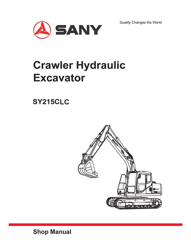
Sany SY215C LC excavator pdf shop manual
SANY-SY215CLC-SM
$28.90
No tax
Format: PDF
Pages: 670
File size: 12.93 MB
Language: English
Models: SY215CLC
Create an account and join to our cumulative discounts program. Spend at least $29.9 and get 10.00% discount.
Rating:
(0)
Table of Contents for SANY-SY215CLC-SM-EN manual
- SY215CLC Crawler Hydraulic Excavator Shop Manual
- Shop Manual
- Table of Contents
- Introduction
- 1.1 Safety Notice
- 1.2 How to Read the Shop Manual
- 1.3 Terms for Maintenance Standard
- 1.4 Handling Electrical and Hydraulic Components
- 1.5 Hose Connector
- 1.6 Table of Standard Tightening Torques
- 1.7 Type of Bolts
- 1.8 Tightening Sequence
- 1.9 Maintenance of Half Flanges
- 1.10 Conversion Table
- Shop Safety
- 2.1 Hazard Alert Information
- 2.2 General Shop Safety
- Specifi cations
- 3.1 Dimensions
- 3.2 Working Ranges
- 3.3 Technical Specifi cations
- 3.4 Weight Table
- 3.5 Fuel and Coolant
- 3.6 Engine Performance Curve
- Structure and Function
- 4.1 Engine and Cooling System
- 4.2 Power Train
- 4.3 Undercarriage and Frame
- 4.4 Hydraulic System, Part 1
- 4.5 Hydraulic System, Part 2
- 4.6 Hydraulic System, Part 3
- 4.7 Air Conditioning System
- 4.8 Engine Control
- 4.9 Electrical Control System
- 4.10 Monitoring System
- Standard Values
- 5.1 Standard Values for Chassis-related Parts
- Testing and Adjusting
- 6.1 Engine Speed Test and Calibrate
- 6.2 Exhaust Gas Color Test
- 6.3 Engine Speed Sensor Adjust
- 6.4 A/C Compressor Belt Tension Test and Adjust
- 6.5 Swing Bearing Clearance Measure
- 6.6 Track Tension Test and Adjust
- 6.7 Hydraulic Pressure in Hydraulic Circuits Test and Adjust
- 6.8 Control Circuit Oil Pressure Test and Adjust
- 6.9 Solenoid Valve Output Pressure Measure
- 6.10 Pilot Valve Output Pressure Measure
- 6.11 Pilot Valves (Work Equipment and Swing) Adjust
- 6.12 Work Equipment Hydraulic Drift Test
- 6.13 Residual Pressure in Hydraulic Circuit Release
- 6.14 Oil Leakage Measure
- 6.15 Air in Each Component Bleed
- Troubleshooting
- 7.1 Points to Remember When Troubleshooting
- 7.2 Sequence of Events in Troubleshooting
- 7.3 Troubleshooting Procedures
- 7.4 Connectors
- 7.5 Failure Symptoms and Service Codes
- Disassembly and Assembly
- 8.1 Reading Guide
- 8.2 Operating Precautions
- 8.3 Radiator AS Remove and Install
- 8.4 Engine and Hydraulic Pump AS Remove and Install
- 8.5 Final Drive AS Remove and Install
- 8.6 Final Drive AS Disassemble and Assemble
- 8.7 Swing Motor and Swing Drive AS Remove and Install
- 8.8 Swing Motor and Swing Drive AS Disassemble and Assemble
- 8.9 Idler AS Disassemble and Assemble
- 8.10 Sprocket Remove and Install
- 8.11 Track AS Remove and Install
- 8.12 Swing Bearing AS Remove and Install
- 8.13 Swing Platform AS Remove and Install
- 8.14 Swivel Joint AS Remove and Install
- 8.15 Swivel Joint AS Disassemble and Assemble
- 8.16 Hydraulic Tank AS Remove and Install
- 8.17 Control Valve AS Remove and Install
- 8.18 Hydraulic Pump AS Remove and Install
- 8.19 Middle Oil Seal (Hydraulic Pump Input Shaft)Remove and Install
- 8.20 Pilot Valve AS (Work Equipment) Disassemble and Assemble
- 8.21 Pilot Valve AS (Travel) Disassemble and Assemble
- 8.22 Hydraulic Cylinder AS Disassemble and Assemble
- 8.23 Work Equipment AS Remove and Install
- 8.24 Air Conditioner AS Remove and Install
- 8.25 Counterweight AS Remove and Install
- 8.26 Cab AS Remove and Install
- 8.27 Cab Window Glass – Disassemble and Assemble
- 8.28 Front Window AS Disassemble and Assemble
- 8.29 Monitor Remove and Install
- 8.30 Controller AS Remove and Install
- 8.31 Radio
- 8.32 Battery
- 8.33 Start Switch
- 8.34 Fuse Box
- 8.35 Wiper
- 8.36 Relay
- 8.37 Sensor
- 8.38 Connector Terminals Insert and Remove
- System Schematics
- Document type
- Shop manual
- Language
- English
- Machinery type
- excavator

Tap to zoom