Shopping Cart
There are no more items in your cart
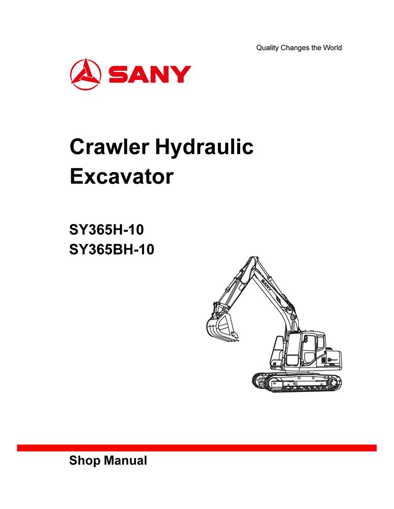
Sany SY365H-10, SY365BH-10 excavator pdf shop manual
SANY-SY365BH-10-SM
$28.90
No tax
Format: PDF
Pages: 592
File size: 16.86 MB
Language: English
Models: SY365H-10, SY365BH-10
Create an account and join to our cumulative discounts program. Spend at least $29.9 and get 10.00% discount.
Rating:
(0)
Table of Contents for SANY-SY365BH-10-SM-EN manual
- Crawler Hydraulic Excavator SY365H(BH)-10 Shop Manual
- 1 Foreword
- 1.1 How to read this manual
- 1.2 Notes on standard terminology for maintenance
- 1.3 Treatment of electrical and hydraulic components
- 1.4 Pipe connector
- 1.5 Bolts and nuts
- 1.6 Maintenance of split flange
- 1.7 Conversion table
- 2 Safety
- 2.1 Instructions for safety signs
- 2.2 General precautions
- 2.3 Preparations before maintenance
- 2.4 Precautions for maintenance
- 2.5 Miscellaneous
- 3 Technical Specifications
- 3.1 Specified dimension
- 3.2 Technical specifications
- 3.3 Weight table
- 3.4 Oil, fuel and coolant
- 3.5 Engine curve
- 4 Structure and Function
- 4.1 Engine and cooling system
- 4.2 Powertrain
- 4.3 Lower structure
- 4.4 Hydraulic system, part 1
- 4.5 Hydraulic system, part 2
- 4.6 Hydraulic system, part 3
- 4.7 Control system
- 4.8 Work equipment
- 4.9 A/C system
- 4.10 Engine control
- 4.11 Electrical control system
- 4.12 Display system
- 5 Standard values of components
- 5.1 Table of Standard Values of Engine Related Components
- 5.2 Table of Standard Values of Body Related Components
- 6 Test and adjustment
- 6.1 Exhaust smoke color measurement
- 6.2 Valve clearance adjustment
- 6.3 Inspection and adjustment of A/C compressor belt tensioner
- 6.4 Measurement of swing bearing clearance
- 6.5 Inspection and adjustment of track tensioner
- 6.6 Inspection and adjustment of hydraulic oil in the work equipment, swing and travel hydraulic lines
- 6.7 Inspection and adjustment of oil pressure in control oil line
- 6.8 Measuring the output pressure of solenoid valve
- 6.9 Measuring the output pressure of pilot valve
- 6.10 Adjustment of work equipment and swing pilot valve
- 6.11 Inspection of the drift of hydraulic cylinder for work equipment
- 6.12 Release of residual pressure from hydraulic lines
- 6.13 Leakage measurement
- 6.14 Bleeding air from each system
- 7 Fault diagnosis and troubleshooting
- 7.1 Precautions during fault diagnosis
- 7.2 Inspection before fault diagnosis
- 7.3 Fault-Find out the symptoms and fault diagnosis numbers
- 7.4 Fault diagnosis of electrical system
- 7.5 Circuit Diagram of Electrical Control System
- 7.6 SWP connector
- 7.7 A/AMP connector
- 7.8 DT connector
- 7.9 Fault diagnosis with DTC displayed
- 7.10 Fault diagnosis of electrical system (mode E)
- 7.11 Table of Hydraulic and Mechanical System (mode H)
- 8 Removal and Installation
- 8.1 Tips
- 8.2 Precautions during operation
- 8.3 Removal and installation of starter motor assembly
- 8.4 Removal and installation of flywheel
- 8.5 Removal and installation of cylinder head cover
- 8.6 Removal and installation of oil pan
- 8.7 Removal and installation of rear oil seal of crankshaft
- 8.8 Removal and installation of fuel injector
- 8.9 Removal and installation of EGR valve and EGR cooler
- 8.10 Removal and installation of radiator assembly
- 8.11 Removal and installation of engine and hydraulic pump assembly
- 8.12 Removal and installation of final drive assembly
- 8.13 Disassembly and reassembly of final drive assembly
- 8.14 Removal and installation of swing motor and swing mechanism assembly
- 8.15 Disassembly and reassembly of swing motor and swing mechanism assembly
- 8.16 Disassembly and reassembly of idler assembly
- 8.17 Removal and installation of driving wheel
- 8.18 Removal and installation of track assembly
- 8.19 Removal and installation of swing bearing assembly
- 8.20 Removal and installation of turntable assembly
- 8.21 Removal and installation of center swivel joint assembly
- 8.22 Disassembly and reassembly of center swivel joint assembly
- 8.23 Removal and installation of hydraulic tank assembly
- 8.24 Removal and installation of control valve assembly
- 8.25 Removal and installation of hydraulic pump assembly
- 8.26 Removal and installation of oil seal in the input shaft of hydraulic pump
- 8.27 Disassembly and reassembly of pilot valve assembly of work equipment
- 8.28 Disassembly and reassembly of travel pilot valve assembly
- 8.29 Disassembly and reassembly of hydraulic cylinder assembly
- 8.30 Removal and installation of work equipment assembly
- 8.31 Removal and installation of A/C assembly
- 8.32 Removal and installation of counterweight assembly
- 8.33 Removal and installation of cab assembly
- 8.34 Removal and installation of cab windows
- 8.35 Removal and installation of front window assembly
- 8.36 Removal and installation of display screen
- 8.37 Removal and installation of controller assembly
- 8.38 Radio
- 8.39 Battery
- 8.40 Ignition key switch
- 8.41 Fuse box
- 8.42 Wiper
- 8.43 Relay
- 8.44 Sensor
- 8.45 Terminal insertion and removal
- 9 Hydraulic and Electrical Diagrams
- 9.1 Hydraulic oil circuit diagram
- 9.2 Electrical diagram of body
- 9.3 Electrical diagram of control switch
- 9.4 Electrical diagram of cab
- 9.5 Electrical diagram of A/C group
- 9.6 Electrical diagram of display screen
- Document type
- Shop manual
- Language
- English
- Machinery type
- excavator

Tap to zoom