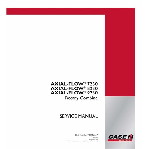
Case IH 7230, 8230, 9230 Axial-Flow combine pdf service manual  - Case IH manuals - CASE-48040837-EN
English

Case IH 7230, 8230, 9230 Axial-Flow combine pdf service manual

CASE-48040837-EN
$103.90
No tax

Format: PDF

Pages: 4101

File size: 200.43 MB

Language: English

Models: AXIAL-FLOW® 7230, AXIAL-FLOW® 8230, AXIAL-FLOW® 9230 rotary combine

Rating:
(0)

Create an account and join to our cumulative discounts program. Spend at least 15$ and get 10.00% discount.

A free preview file lets you see document content, and a link is available in the Attachments section. The manuals come in a convenient PDF format. You can easily open PDF files on a computer, Mac or PC, any smartphone or a tablet. Each document has passed the integrity test of our specialists.

You purchased manuals are available in your account, and you can re-download them at no additional charge. Your account is open to you 24 hours a day, 7 days a week. If you have any problems downloading a file, please, contact us, and we will provide you with an alternative download link.

All major credit/debit cards and PayPal are accepted. No additional taxes or fees. We guarantee your satisfaction!

SATISFACTION GUARANTEE
SHOP WITH CONFIDENCE
SECURE PAYMENT
INSTANT DOWNLOAD
 

Case IH 7230, 8230, 9230 Axial-Flow combine pdf service manual is available for instant download after purchase. Download a free preview pdf file of the original document, and decide whether it suits your needs. This preview file in the Attachments section includes the initial part of the main document, about 5% of the pages, and you may get acquainted with the contents of the document.

Document type
Service manual
Language
English
Machinery type
combine

Case IH is a global agricultural equipment manufacturer that provides a wide range of farm machinery and equipment for different agriculture sectors, including planting, harvesting, tillage, and material handling. The company has a long history, dating back to the 1840s when it started as a company producing threshing machines.

Over the years, the company has grown and expanded its operations, now producing equipment for various agriculture industries. Case IH offers a wide range of products, including tractors, combine harvesters, planters, tillage tools, balers, and sprayers, among others.

In terms of manuals for their products, Case IH provides comprehensive and detailed manuals for all their equipment. These manuals are designed to help farmers and operators better understand and operate the equipment safely and efficiently.

The manuals include detailed information about the equipment, including specifications, features, and benefits, as well as detailed instructions on how to use and maintain the equipment. They also provide troubleshooting tips and other useful information that can help farmers and operators keep the equipment in good working condition.

In addition to printed manuals, Case IH also provides electronic manuals that can be accessed online or through a mobile device. These electronic manuals offer the same level of detail and information as printed manuals, but they are more convenient and accessible.

Overall, Case IH is a reliable and trusted brand that provides high-quality agricultural equipment and detailed manuals to support farmers and operators in their daily operations.

In 1842 businessman Jerome Case established JI Case in Rochester, Wisconsin. A year later, the company changed the place of registration to the town of Racine in the same state, as its location was closer to the water and facilities on which it was possible to build and repair agricultural machinery, the production of which decided to tackle Jerome. At the new location, the company was registered under the name Racine Threshing Machine Works. In 1963, Casey's business associates were three farmers: Massena Erskine, Robert Baker, and Stefan Bull. Later they were given the nickname of the Big Four in agricultural production, and Case himself was later noted as the first American to use a steam engine for agriculture.

In 1865, the symbol of the company was presented - the eagle, completely repeating the talisman of the legendary Wisconsin regiment of the Civil War in the United States. In turn, the first design success of Kais was the steam harvester, created in 1869. Later this machine was placed in the Smithsonian Museum in Washington, DC. With his combines, Jerome Case took first place in 1879 at the Paris exhibition in France. These several cars were the first machines of Case, who were sent abroad. The first of those thousands that were later exported internationally in large quantities.

At the same time, Case also created a steam tractor based on one of its engines. In 1884, Jerome Case visited one of the farms in Minnesota, where his technique was used, as he heard rumors that the car was not working. It turned out to be true. Outraged by the fact that he would not be able to take the car with him and repair it, the next day Jerome burned it, and when he returned to Wisconsin, he ordered the owner of the destroyed tractor to be delivered to the owner. The farm was later named after Keyes, which, by the way, is not at all surprising.

In 1890, Case expanded its production, reaching South America - the plant was opened in Argentina. A year later, Jerome Case died at the age of 72 years. At that time, Case was the most productive company in the whole of North America: Case Company produced agricultural machinery with engines ranging from 9 horsepower to 80. In addition, a batch of 110 horsepower tractors with a two-tier cab was produced, as well as nine tractors Capacity of 150 horsepower.

Using the production of gasoline engines Case Company took up in 1895. In 1899 the enterprise came out to the Russian market, and in 1904 presented to the consumer its first combine completely made of steel. In the same year, the first tractor with an internal combustion engine was produced, and in addition, the company was firmly entrenched in Europe. This was shown by the results of the contest, within which it became clear that the Case Company technique is found more often than other equipment on the arable lands of the "old world".

By that time, the range of Case Company products was very diverse: from combines, tractors, and graders to water carriers, buggies, plows, and even simple cars. However, the production of civilian auto Case Company engaged in a relatively short period of time. Of the successes in this industry is worth noting only 7-seat tourist car, released in 1920.

At the beginning of the twentieth century, it became clear to everyone that the future belongs to gasoline engines. The management of the Case Company invited rider Joe Jaggersberg, who agreed to test their new engine on the Indianapolis 500 race in 1911. And the following year the company started to produce engine oil. Also for several years, Case Company was engaged in the production of kerosene tractors.

Oddly enough, the European sales of the company were positively influenced by the outbreak of the First World War: almost every farmhand was drafted to the front, and farmers had to get out to save the harvest.

In 1919, an event occurred that affected the future of Case Company - an enterprise called John Deere Company broke into the market of harvesters. The response of their competitors from International Harvester was a new course for the acquisition of the P & O Plowing Company from Canton, Illinois, and Chattanooga Plowin from Chatanuga, Tennessee. Then Henry Ford, with his Fordson Tractor company, intervened in the same branch of the market.

This is how the "Tractor War" began in 1923, which took place between Ford Motor Company, John Deere, Case, and International Harvester. Case then became part of International Harvester, thus transforming itself into Case-IHC. But even after the merger, the company controlled only 9% of the market, while 71% accounted for the company Ford. In the same year, the company Keisa celebrated the anniversary - was produced 100-thousand harvester in the history of production. And in 1928 the enterprise expected another change of name - this time the company became known as J.I. Case Company.

A year before, the factories had stopped producing legendary steam tractors, and the priority was given to internal combustion engines. Equipped with different types of engines, the tractors also differed in color. Steam tractors were painted in black and green colors, and petrol - in gray (later they became orange, while the excavators were painted with red and yellow flowers).

In 1929, the company continued its policy of expanding the international market in Australia, Mexico, and Sweden. In the same year, the first tracked tractor J.I. Case Company. During 1940 in the state of Nebraska there were tests of a diesel tractor WD-40. A little later in the same year, the company introduced tractors of the S and V.

During the Second World War II Case Company produced artillery shells, spare parts for B-26 airplanes, bombs and Sherman tanks. In 1941, the company opened three new factories in the United States of America. A year later, the light came out Model 123 SP. In addition, 1942 was significant in the history of the company by the appearance of the first cotton picking machine, which also fell into the Smithsonian Museum.

In 1947, the company's logo changed - the name "C" disappeared from the name, and the logo itself was now a person sitting in the tractor. This emblem was developed by the famous industrial designer Raymond Lowe.

In 1958, another foreign plant opened in Doncaster, Great Britain. During the next 31 years, the company significantly globalized. Many other enterprises managed to join Case in such a long period of time. So in 1962, the company J.I. Case bought out the corporation American Tractor, which then led the US in the volume of production of excavators and trucks. Thanks to this merger, in 1967 Case Company was able to present to the public the most successful excavator model 250C Construction King, which became a synonym for this type of equipment in the United States.

In 1984, many units of International Harvester merged with J.I. Case Company and began to produce products under the brand name Case International (later Case IH). Until 1988, 94 products were produced under the name CASE, and only then appeared Magnum. In 1996, the company acquired the Australian manufacturer of tractors Steyr Tractor.

Case Corporation merged with New Holland N.V., becoming CNH, and since November 1999 - CNH Global. Due to the merger, CNH Global had to sell factories in Doncaster, United Kingdom, and Winnipeg, Canada. Such a merger gave an optimistic mood and gave hope to Case Corporation's prosperity in the European market, so in 2006 a business plan was created to return the company to the status of "international". For this, the old International Harvester logo was returned, and in addition, there were significant differences between the two existing brands within the corporation.
Less
  • SERVICE MANUAL AXIAL-FLOW COMBINES
  • Contents
  • INTRODUCTION
    • Basic instructions Important notice regarding equipment servicing
    • Safety rules Signal word definitions
    • Personal safety
    • Safety rules Ecology and the environment
    • Safety rules Repair and maintenance
    • Basic instructions Shop and assembly
    • Torque Minimum tightening torques for normal assembly
    • Torque Standard torque data for hydraulics
    • Basic instructions Chain Wear Tables Roller Chains
    • Capacities
    • Machine specifications
    • General specification
    • Product identification Machine orientation
  • Engine 10
    • Air cleaners and lines 202
      • Air intake system Remove from 8230 and 9230
      • Air intake system Install to 8230 and 9230
      • Air intake system Remove from 7230
      • Air intake system Install to 7230
    • Fuel tanks 216
      • Fuel tank Capacity
    • Fuel injection system 218
      • Fuel injection system Dynamic description Electrical
      • Common rail Overview
      • Fuel injectors Overview Fuel actuators
      • Fuel injectors Dynamic description Electrical
      • Common rail Remove
      • Common rail Install
    • Aftercooler 310
      • Aftercooler Remove charge air cooler
      • Aftercooler Install charge air cooler
      • Aftercooler Remove charge air cooler
      • Aftercooler Install charge air cooler
    • Engine cooling system 400
      • Water pump Overview
      • Coolant thermostat Overview
      • Engine cooling system Emptying
      • Radiator Remove Engine Coolant Radiator
      • Radiator Install Engine Coolant Radiator
      • Deaeration tank Remove
      • Deaeration tank Install
      • Water pump Remove
      • Water pump Install
      • Coolant thermostat Remove
      • Coolant thermostat Install
    • Fan and drive 414
      • Fan and drive Remove
      • Fan and drive Install
      • Fan and drive Remove
      • Fan and drive Install
      • Belt Remove
      • Belt Install
      • Belt tensioner Remove
      • Belt tensioner Install
    • Rotary screen 418
      • Rotary screen Repair
      • Radiator wiper Remove
      • Radiator wiper Install
      • Radiator wiper Remove
      • Radiator wiper Install
      • Rotary screen drive belt or chain Remove belt
      • Rotary screen drive belt or chain Install belt
    • Engine air compressor 450
      • Air compressor General specification
      • Compressed air tank Relief valve General specification
      • Engine air compressor Overview Air Compressor
      • Air compressor Drawing
      • Compressed air tank Detailed view
      • Engine air compressor Test
      • Engine air compressor Service instruction
    • Selective Catalytic Reduction (SCR) exhaust treatment 500
      • Selective Catalytic Reduction (SCR) exhaust treatment Overview
  • Main gearbox and drive 14
    • Main gearbox and drive 100
      • Main gearbox and drive Special tools
      • Main gearbox and drive Overview PTO Gearbox Shaft Chart
      • Main gearbox and drive Overview
      • Main gearbox and drive Dynamic description of the continuous variable transmission (CVT) control valve
      • Main gearbox and drive Remove of the PTO Gearbox Assembly
      • Main gearbox and drive Install
      • Main gearbox and drive Assemble PTO Gearbox "OFF Frame"
      • Main gearbox and drive Disassemble PTO Gearbox
      • Main gearbox and drive Place on stand Mounting the PTO gearbox on a Stand.
      • Main gearbox and drive Drain fluid
      • Main gearbox and drive Filling
      • Main clutch Disassemble Clutch Shaft
      • Main clutch Assemble Clutch Shaft
      • Main clutch Remove the Beater/Chopper Clutch Shaft "In Frame"
      • Main clutch Install Beater/Chopper Clutch Shaft
  • Transmission 21
    • Mechanical transmission hydraulic components 100
      • Mechanical transmission hydraulic components Overview
      • Mechanical transmission hydraulic components Dynamic description
      • Mechanical transmission hydraulic components Hydraulic schema
      • Transmission lubrication valve Overview Transmission Lubrication
      • Transmission lubrication valve Pressure test PTO Gearbox Lubrication
      • Transmission cooling and/or lubrication pump Flow test PTO Gearbox Lubrication
    • Mechanical transmission 114
      • Mechanical transmission Torque
      • Mechanical transmission Overview
      • Mechanical transmission Detailed view
      • Mechanical transmission Remove
      • Mechanical transmission Disassemble
      • Mechanical transmission Assemble
      • Mechanical transmission Install
      • Mechanical transmission Adjust shift position sensor
      • Mechanical transmission Service instruction Manual shift
    • Mechanical transmission external controls 130
      • Transmission housing cover Remove
      • Transmission housing cover Install
    • Gearbox internal components 145
      • Drive shaft Sectional view
      • Drive shaft Exploded view
      • Drive shaft Exploded view with Cover
      • Driven shaft Sectional view
      • Driven shaft Exploded view
      • Driven shaft Exploded view with Bearing Caps
      • Shifting disk system Sectional view with Drive Gear
      • Shifting disk system Exploded view with Drive Gear
      • Shifting disk system Sectional view of Shifting Diagram
      • Drive shaft Remove
      • Drive shaft Disassemble
      • Drive shaft Assemble
      • Drive shaft Install
      • Driven shaft Remove
      • Driven shaft Disassemble
      • Driven shaft Assemble
      • Driven shaft Install
      • Internal controls Remove
      • Internal controls Install
      • Shifting disk system Remove
      • Shifting disk system Install
    • Differential 182
      • Differential Sectional view
      • Differential Exploded view
      • Differential Exploded view of Shafts
      • Differential lock lever Overhaul
      • Differential Remove
      • Differential Disassemble
      • Differential Assemble
      • Differential Install
  • Front axle system 25
    • Powered front axle 100
      • Torsion bar Remove
    • Final drive hub, steering knuckles, and shafts 108
      • Final drive Sectional view
      • Final drive Exploded view
      • Planetary drive and hub Exploded view
      • Planetary drive and hub Disassemble
      • Planetary drive and hub Assemble
      • Wheel hub Replace Wheel Bolt Replace
    • Final drives 310
      • Final drive Sectional view
      • Final drive Static description of final drive seals
      • Final drive driving pinion Exploded view
      • Final drive driving pinion Overview
      • Final drive Remove Planetary Type 1:13.09 Ratio
      • Final drive Install Planetary Type 1:13.09 Ratio
      • Final drive Remove Planetary Type 1:13.09 ratio and 1:14.93 ratio
      • Final drive Install Planetary Type 1:13.09 ratio and 1:14.93 ratio
      • Final drive Disassemble Planetary Type 1:13.09 Ratio
      • Final drive Assemble Planetary Type 1:13.09 Ratio
      • Final drive Remove Bull Gear Type 11:111 Ratio
      • Final drive Install Bull Gear Type 11:111 Ratio
      • Final drive Disassemble Bull Gear Type 11:111 Ratio
      • Final drive Visual inspection Bull Gear Type 11:111 Ratio
      • Final drive Assemble Bull Gear Type 11:111 Ratio
      • Final drive driving pinion Disassemble
      • Final drive driving pinion Assemble
      • Driven gears and shaft Output shaft Disassemble
      • Driven gears and shaft Output shaft Assemble
      • Driven gears and shaft Wheel stud Replace
      • Driven gears and shaft Input shaft Remove
      • Driven gears and shaft Input shaft Install
  • Rear axle system 27
    • Powered rear axle 100
      • Powered rear axle Overview
      • Powered rear axle Dynamic description Electrical
      • Rear axle Height adjust
    • Final drive hub, steering knuckles, and shafts 124
      • Steering knuckle housing hub Disassemble
      • Steering knuckle housing hub Assemble
    • Non-powered rear axle 550
      • Wheel hub Install
  • Hydrostatic drive 29
    • Transmission and steering hydrostatic control 100
      • Transmission and steering hand control Transmission command Overview Ground Speed Potentiometer
      • Transmission and steering hand control Transmission command Static description for fixed speed motors.
      • Transmission and steering hydrostatic control Pressure test for the servo.
      • Hydrostatic drive system valves Pressure test
    • Two-speed assembly 134
      • Two-speed assembly Dynamic description Electrical
    • Hydrostatic transmission 202
      • Hydrostatic transmission General specification
      • Hydrostatic transmission Overview
      • Hydrostatic transmission Hydraulic schema
      • Hydrostatic transmission Dynamic description
      • Hydrostatic transmission Electrical schema Circuit Operation
      • Hydrostatic transmission Dynamic description of the charge pressure system
      • Hydrostatic transmission Flow test Charge Supply
      • Hydrostatic transmission Filling
    • Pump and motor components 218
      • Pump General specification
      • Motor General specification
      • Pump and motor components Overview of the Charge Pump
      • Pump Component identification
      • Pump Static description
      • Pump Dynamic description Hydrostatic Ground Drive
      • Pump Hydrostatic schema Ground Drive
      • Pump External view Hydrostatic Ground Drive
      • Pump Dynamic description of the pump control valve
      • Hydrostatic system feed pump Overview
      • Motor Static description Ground Drive Motor
      • Motor Dynamic description Hydrostatic Ground Drive
      • Motor Exploded view
      • Motor Exploded view of the Power Rear Axle (PRA) motor
      • Motor Dynamic description of the Powered Rear Axle (PRA) motor
      • Motor Dynamic description of the Variable Ground Drive Motor
      • Motor valves Dynamic description
      • Pump Check
      • Pump Remove Hydrostatic Ground Drive Pump
      • Pump Install Hydrostatic Ground Drive Pump
      • Motor Check
      • Motor Remove
      • Motor Install
      • Motor Leakage test Case Drain Flow
      • Hydraulic motor Bleed
      • Motor Remove Powered Rear Axle (PRA) motor
      • Motor Disassemble Powered Rear Axle (PRA) motor
      • Motor Assemble Powered Rear Axle (PRA) motor
      • Hydraulic motor Install
    • Rear hydrostatic transmission 300
      • Drive system Control valve General specification Powered Rear Axle
      • Rear hydrostatic transmission Detailed view Powered Rear Axle
      • Drive system Control valve Exploded view Powered Rear Axle
      • Drive system Control valve Dynamic description Powered Rear Axle
      • Two-speed valve Exploded view
      • Hose Plumbing schema Powered Rear Axle Hoses
      • Drive system Control valve Overhaul
      • Drive system Control valve Replace
      • Drive system Control valve Pressure test
      • Drive system Control valve Test Selector Spool
      • Drive system Control valve Test Flow Regulators
      • Rear hydrostatic transmission Problem solving
      • Two-speed valve Testing Electrical Circuit
  • Power Take-Off (PTO) 31
    • Front Power Take-Off (PTO) 146
      • Front Power Take-Off (PTO) Remove Header drive gearbox
      • Front Power Take-Off (PTO) Install Header drive gearbox
      • Front Power Take-Off (PTO) Disassemble Header drive gearbox
      • Front Power Take-Off (PTO) Assemble Header drive gearbox
      • Engine gearbox Remove
      • Engine gearbox Install
      • Engine gearbox Disassemble
      • Engine gearbox Assemble
      • Drive shaft Remove
      • Drive shaft Install
      • Drive shaft Replace Universal Joint
  • Brakes and controls 33
    • Parking brake or parking lock 110
      • Parking brake or parking lock General specification
      • Parking brake or parking lock Dynamic description
      • Parking brake control valve or manifold Overview Park Brake Solenoid
      • Parking brake control valve or manifold Parking brake override Dynamic description
      • Parking brake internal controls Sectional view
      • Parking brake or parking lock Bleed
      • Parking brake internal controls Replace
      • Parking brake internal controls Disassemble
      • Parking brake internal controls Assemble
      • Parking brake internal controls Travel adjust Park Brake
      • Parking brake discs Remove
      • Parking brake discs Install
      • Parking brake caliper Remove
      • Parking brake caliper Install
    • Hydraulic service brakes 202
      • Hydraulic service brakes General specification
      • Brake master cylinder Dynamic description of Brake Cylinders
      • Hydraulic service brakes Bleed
      • Brakes Replace Pad
      • Brakes Remove Calipers and Discs
      • Brakes Install Calipers and Discs
  • Hydraulic systems 35
    • Hydraulic systems 000
      • Hydraulic systems General specification
      • Hydraulic systems Special tools
      • Hydraulic systems Dynamic description
      • Hydraulic systems Overview
      • Hydraulic systems Hydraulic schema
      • Hydraulic systems External view
      • Hydraulic systems Hydraulic schema Control Pressure
      • Hydraulic systems Overview
      • Hydraulic systems Leakage test Control Pressure Flow
    • Pump control valves 102
      • Pump control valves Dynamic description Regulated Pressure
      • Pump control valve Overview
      • Signal valve Overview
      • Signal valve Hydraulic schema
      • Pump control valve Pressure test Control Pressure Test
      • Pump control valve Pressure test PTO or CVT Valve
      • Pump control valve Leakage test Supply Line to PTO Valves
    • Variable displacement pump 106
      • Variable displacement pump Dynamic description
      • Variable displacement pump Hydraulic schema
      • Variable displacement pump Static description
      • Variable displacement pump Pressure test Low Pressure Standby
      • Variable displacement pump Pressure test High Pressure Standby
      • Variable displacement pump Flow test PFC Pump
      • Variable displacement pump Pressure test Regulated Pressure
      • Pump Remove PFC System Pump
      • Pump Install PFC System Pump
    • Auxiliary hydraulic pump 220
      • Auxiliary hydraulic pump Overview Triple Gear Pump
      • Auxiliary hydraulic pump Flow test Control Pressure Pump
      • Auxiliary hydraulic pump Remove Triple Gear Pump
      • Auxiliary hydraulic pump Install Triple Gear Pump
    • Reservoir, cooler, and filters 300
      • Oil reservoir Overview
      • Oil filters Overview
      • Oil filters Overview Charge Pressure Filter
      • Oil cooler/Heat exchanger Overview Auxiliary Oil Cooler
      • Oil cooler/Heat exchanger Remove
      • Oil cooler/Heat exchanger Install
      • Oil cooler/Heat exchanger Remove
      • Oil cooler/Heat exchanger Install
    • Safety and main relief valves 350
      • Main relief valve Pressure test Bench Testing Components
    • Main control valve 359
      • Stacked control valves Overview Main Stack Valve
      • Stacked control valves Hydraulic schema Main Stack
      • Stacked control valves Overview Feeder valve
    • Header or attachment height system 410
      • Distribution block solenoid valve Header lift valve Dynamic description
      • Distribution block solenoid valve Header lift valve Dynamic description Electrical
      • Positioning accumulator Valve Dynamic description Electrical
      • Distribution block solenoid valve Problem solving
    • Header or attachment tilting system 415
      • Header or attachment tilting system General specification
      • Control valve Lateral tilt valve Dynamic description Electrical
      • Tilting support Remove Tilting Header Mount Frame
      • Tilting support Install Tilting Header Mount Frame
    • Grain tank unload system 440
      • Command valve Unload swing Dynamic description Electrical
      • Unloading hydraulic motor Remove
      • Unloading hydraulic motor Install
    • Reel control system 518
      • Reel control valve Raise and lower Overview
      • Reel control valve Fore and aft Overview
      • Reel control valve Drive Overview Reel Drive
      • Reel control valve Raise and lower Dynamic description Electrical
      • Reel control valve Fore and aft Dynamic description Electrical
      • Reel control valve Drive Dynamic description Electrical
    • Crop processor system 536
      • Feeder housing pump Pressure test Feeder CVT
      • Feeder housing pump Remove Feeder Pump
      • Feeder housing pump Install Feeder Hydro Pump
      • Threshing pump Flow test Charge Supply
      • Threshing pump Pressure test Rotor CVT Pump Drive
      • Threshing pump Leakage test Rotor Hydro Case Drain Flow
      • Threshing pump Remove
      • Threshing pump Install
      • Feeder housing motor Leakage test Case Drain Flow
      • Threshing motor Remove Hydraulic Rotor Motor
      • Threshing motor Install Hydraulic Rotor Motor
    • Chaff spreader control 796
      • Chaff spreader hydraulic motor Special tools
      • Control valve Dynamic description Electrical Spreader valve
      • Chaff spreader hydraulic motor Exploded view
      • Chaff spreader hydraulic motor Disassemble
      • Chaff spreader hydraulic motor Assemble
  • Steering 41
    • Steering control 101
      • Steering column Remove
      • Steering column Disassemble
      • Steering column Assemble
      • Steering column Install
    • Hydraulic control components 200
      • Hydraulic control components Dynamic description Steering Circuit
      • Hydraulic control components Component identification
      • Power steering control valve Dynamic description Electrical
      • Main priority valve Hydraulic schema
      • Hydraulic control components Toe in adjust
      • Steering circuit relief valve Pressure test Steering Relief Setting
    • Cylinders 216
      • Rear axle steering cylinder Static description
    • Autoguidance steering 432
      • Autoguidance valve General specification
      • Autoguidance valve Remove
      • Autoguidance valve Install
      • Autoguidance valve Assemble
  • Wheels 44
    • Front wheels 511
      • Front wheels Torque
      • Front wheels Install dual wheels
      • Front wheels Install
    • Rear wheels 520
      • Rear wheel Torque
  • Tracks and track suspension 48
    • Track frame and driving wheels 130
      • Track frame Remove
      • Track frame Install
      • Track frame Undercarriage Remove
      • Track frame Undercarriage Install
      • Track support Isolation mount Remove
      • Track support Isolation mount Install
  • Cab climate control 50
    • Heating 100
      • Cab heater Static description
      • Heater core Remove
      • Heater core Install
      • Heater core Remove
      • Heater core Install
      • Cab heater Preliminary test
      • Heater control valve Remove
      • Heater control valve Install
      • Heater control valve Remove
      • Heater control valve Install
      • Temperature control Replace Temperature sensor near blower motor
      • Temperature control Replace Temperature sensor behind left-hand storage area
      • Temperature control Replace Temperature sensor behind cab recirculation air filter
      • Heater control valve Testing
    • Ventilation 104
      • Ventilation Dynamic description
      • Ventilation Remove HVAC Assembly
      • Ventilation Install HVAC Assembly
      • Air filter Recirculation filter Remove
      • Air filter Recirculation filter Install
      • Air filter Separator filter Remove
      • Air filter Separator filter Install
      • Air flow distribution system Remove Blower motor
      • Air flow distribution system Install Blower motor
      • Air flow distribution system Remove Blower linear driver
      • Air flow distribution system Install Blower linear driver
    • Air conditioning 200
      • Air conditioning Special tools
      • Air-conditioning compressor Torque
      • Receiver-dryer Service limits
      • Air conditioning Static description
      • Air conditioning Dynamic description A/C thermal operation
      • Air-conditioning compressor Static description
      • Air-conditioning compressor Magnetic clutch Exploded view
      • Air-conditioning compressor Static description SP-15 PAG oil adjusting
      • Air-conditioning compressor Magnetic clutch Dynamic description Electrical
      • Compressor drive belt Static description
      • Air-conditioning condenser Static description
      • Receiver-dryer Static description
      • Expansion valve Dynamic description
      • Air-conditioning evaporator Static description
      • Air conditioning Leakage test
      • Air conditioning Service instruction
      • Air conditioning Pressure test
      • Air conditioning Replace Low pressure switch
      • Air-conditioning compressor Magnetic clutch Remove
      • Air-conditioning compressor Magnetic clutch Install
      • Air-conditioning compressor Magnetic clutch Adjust air gap
      • Air-conditioning compressor Magnetic clutch Test
      • Air-conditioning compressor Level make up Dipstick Method
      • Air-conditioning compressor Level make up SP-15 PAG oil addition
      • Air-conditioning compressor Remove (from Cursor 9 engine)
      • Air-conditioning compressor Install (on Cursor 9 engine)
      • Air-conditioning compressor Remove (from Cursor 10 Engine)
      • Air-conditioning compressor Install (on Cursor 10 Engine)
      • Air-conditioning compressor Remove (from Cursor 13 Engine)
      • Air-conditioning compressor Install (on Cursor 13 Engine)
      • Air-conditioning condenser Remove
      • Air-conditioning condenser Install
      • Receiver-dryer Remove
      • Receiver-dryer Install
      • Expansion valve Remove
      • Expansion valve Install
      • Expansion valve Test
      • Expansion valve Remove
      • Expansion valve Install
      • Air-conditioning evaporator Remove
      • Air-conditioning evaporator Install
      • Air-conditioning evaporator Remove Temperature sensor
      • Air-conditioning evaporator Install Temperature sensor
      • Air-conditioning evaporator Remove
      • Air-conditioning evaporator Install
      • Drain lines Check Air conditioner drain hose outlets
      • Air conditioning Troubleshooting General
      • Air conditioning Troubleshooting Fault Codes
      • Air conditioning Problem solving Pressure Test Results and Temperature/Pressure Chart
      • Air-conditioning compressor Magnetic clutch Testing
      • Expansion valve Testing
  • Electrical systems 55
    • Engine control system 015
      • Engine Control Unit (ECU) Electrical test Dosing Control Unit (DCU) verification
    • Harnesses and connectors 100
      • Wiring harnesses Electrical schematic sheet 02 SH02 STARTING
      • Wire connectors Component diagram 00
      • Wire connectors Component diagram 01
      • Wire connectors Component diagram 02
      • Wire connectors Component diagram 03
      • Wire connectors Component diagram 04
      • Wire connectors Component diagram 05
      • Wire connectors Component diagram 06
      • Wire connectors Component diagram 07
      • Wire connectors Component diagram 08
      • Wire connectors Component diagram 09
      • Wire connectors Component diagram 10
      • Wire connectors Component diagram 11
      • Wire connectors Component diagram 12
      • Wire connectors Component diagram 13
      • Wire connectors Component diagram 14
      • Wire connectors Component diagram 15
      • Wire connectors Component diagram 16
      • Wire connectors Component diagram 17
      • Wire connectors Component diagram 18
      • Wire connectors Component diagram 19
      • Wire connectors Component diagram 20
      • Wire connectors Component diagram 21
      • Wire connectors Component diagram 22
      • Wire connectors Component diagram 23
      • Wire connectors Component diagram 24
      • Wire connectors Component diagram 25
      • Wire connectors Component diagram 26
      • Wire connectors Component diagram 27
      • Wire connectors Component diagram 28
      • Wire connectors Component diagram 29
      • Wire connectors Component diagram 30
      • Wire connectors Component diagram 31
      • Wire connectors Component diagram 32
      • Wire connectors Component diagram 33
      • Wire connectors Component diagram 34
      • Wire connectors Component diagram 35
      • Wire connectors Component diagram 36
      • Wire connectors Component diagram 38
      • Wire connectors Component diagram 39
      • Wire connectors Component diagram 40
      • Wire connectors Component diagram 41
      • Wire connectors Component diagram 42
      • Wire connectors Component diagram 43
      • Wire connectors Component diagram 44
      • Wire connectors Component diagram 45
      • Wire connectors Component diagram 46
      • Wire connectors Component diagram 47
      • Wire connectors Component diagram 48
      • Wire connectors Component diagram 49
      • Wire connectors Component diagram 50
      • Wire connectors Component diagram 51
      • Wire connectors Component diagram 52
      • Wire connectors Component diagram 57
      • Wire connectors Component diagram 58
      • Wire connectors Component diagram 59
      • Wire connectors Component diagram 60
      • Wire connectors Component diagram 61
      • Wire connectors Component diagram 62
      • Wire connectors Component diagram 63
      • Wire connectors Component diagram 64
      • Wire connectors Component diagram 65
      • Wire connectors Component diagram 66
      • Wire connectors Component diagram 67
      • Wire connectors Component diagram 68
      • Wire connectors Component diagram 70
      • Wire connectors Component diagram 71
      • Wire connectors Component diagram 75
      • Wire connectors Component diagram 83
      • Wire connectors Component diagram 85
      • Wire connectors Component diagram 87
      • Wire connectors Component diagram 90
      • Wire connectors Component diagram 91
      • Wire connectors Component diagram 92
      • Wire connectors Component diagram 93
      • Wire connectors Component diagram 94
      • Wire connectors Component diagram 95
      • Wire connectors Component diagram 97
      • Wire connectors Component diagram 98
      • Wire connectors Component diagram 99
      • Electrical components ECU description
      • Electrical components Sensor description
      • Electrical components Lamp description
      • Electrical components Fuse description
      • Electrical components Voltage source description
      • Electrical components Ground description
      • Electrical components Speaker description
      • Electrical components Power outlet description
      • Electrical components Relay description
      • Electrical components Motor description
      • Electrical components Resistor description
      • Electrical components Switch description
      • Electrical components Solenoid description
    • Warning indicators, alarms, and instruments 408
      • Instrument cluster Detailed view
    • Selective Catalytic Reduction (SCR) electrical system 988
      • Dosing control unit Remove Denox Control Unit (DCU)
      • Dosing control unit Install Denox Control Unit (DCU)
      • Diesel Exhaust Fluid (DEF)/AdBlue®/ARLA supply module Filter Remove
      • Diesel Exhaust Fluid (DEF)/AdBlue®/ARLA supply module Filter Install
      • Diesel Exhaust Fluid (DEF)/AdBlue®/ARLA supply module Cover Remove
      • Diesel Exhaust Fluid (DEF)/AdBlue®/ARLA supply module Cover Install
      • Diesel Exhaust Fluid (DEF)/AdBlue®/ARLA dosing module Disconnect electrical connection to the dosing module
      • Diesel Exhaust Fluid (DEF)/AdBlue®/ARLA dosing module Connect electrical connection to the dosing module
      • Diesel Exhaust Fluid (DEF)/AdBlue®/ARLA dosing module Dosing valve Remove
      • Diesel Exhaust Fluid (DEF)/AdBlue®/ARLA dosing module Dosing valve Install
      • Selective Catalytic Reduction (SCR) harness Remove
      • Selective Catalytic Reduction (SCR) harness Install
      • Selective Catalytic Reduction (SCR) humidity sensor Disconnect
      • Selective Catalytic Reduction (SCR) humidity sensor Connect
      • Selective Catalytic Reduction (SCR) temperature sensors Remove downstream temperature sensor
      • Selective Catalytic Reduction (SCR) temperature sensors Install downstream temperature sensor
      • Selective Catalytic Reduction (SCR) temperature sensors Remove upstream temperature sensor
      • Selective Catalytic Reduction (SCR) temperature sensors Install upstream temperature sensor
      • Selective Catalytic Reduction (SCR) temperature sensors Remove Diesel Oxidation Catalyst (DOC) temperature sensor
      • Selective Catalytic Reduction (SCR) temperature sensors Install Diesel Oxidation Catalyst (DOC) temperature sensor
      • Nitrogen Oxide (NOx) sensor Remove the downstream and upstream NOx sensors
      • Nitrogen Oxide (NOx) sensor Install the downstream and upstream NOx sensors
      • Diesel Exhaust Fluid (DEF)/AdBlue®/ARLA tank level and temperature sensor Remove
      • Diesel Exhaust Fluid (DEF)/AdBlue®/ARLA tank level and temperature sensor Install
      • Coolant control valve solenoid Remove
      • Coolant control valve solenoid Install
      • Diesel Exhaust Fluid (DEF)/AdBlue®/ARLA quality sensor Remove
      • Diesel Exhaust Fluid (DEF)/AdBlue®/ARLA quality sensor Install
      • Ammonia (NH3) sensor Remove
      • Ammonia (NH3) sensor Install
      • E0000-03 Stone Trap Closed Sensor Shorted to high source
      • E0000-04 Stone Trap Closed Sensor Shorted to low source
      • E0000-05 Stone Trap Closed Sensor Line disconnected
      • E0001-03 Bin Covers Open Sensor Shorted to high source
      • E0001-04 Bin Covers Open Sensor Shorted to low source
      • E0001-05 Bin Covers Open Sensor Line disconnected
      • E0002-03 Swath Plate Position Sensor Shorted to high source
      • E0002-04 Swath Plate Position Sensor Shorted to low source
      • E0002-05 Swath Plate Position Sensor Line Disconnected
      • E0003-03 Unload Tube Cradled Sensor Shorted to high source
      • E0003-04 Unload Tube Cradled Sensor Shorted to low source
      • E0003-05 Unload Tube Cradled Sensor Line disconnected
      • E0004-03 Fdr Reverser Disengaged Sensor Shorted to high source
      • E0004-04 Fdr Reverser Disengaged Sensor Shorted to low source
      • E0004-05 Fdr Reverser Disengaged Sensor Line disconnected
      • E0006-03 Return Filter Bypass Switch Shorted to high source
      • E0007-03 Gearbox Filter Bypass Switch Shorted to high source
      • E0008-04 Left Turn Signal Switch Shorted to low source
      • E0009-04 Front Work Lights Switch Shorted to low source
      • E0010-04 Rear Work Lights Switch Shorted to low source
      • E0011-04 Road Lights Switch Shorted to low source
      • E0012-04 Right Turn Signal Shorted to low source
      • E0013-03 Cleaning Fan RPM Sensor Shorted to high source
      • E0013-04 Cleaning Fan RPM Sensor Shorted to low source
      • E0013-05 Cleaning Fan RPM Sensor Line Disconnected
      • E0014-03 Feeder RPM Sensor Shorted to high source
      • E0014-04 Feeder RPM Sensor Shorted to low source
      • E0014-05 Feeder RPM Sensor Line Disconnected
      • E0015-03 Left Returns RPM Sensor Shorted to high source
      • E0015-04 Left Returns RPM Sensor Shorted to low source
      • E0015-05 Left Returns RPM Sensor Line Disconnected
      • E0016-03 Clean Grain Elevator RPM Sensor Shorted to high source
      • E0016-04 Clean Grain Elevator RPM Sensor Shorted to low source
      • E0016-05 Clean Grain Elevator RPM Sensor Line Disconnected
      • E0017-03 Chopper Sel Plate Sensor Shorted to high source
      • E0017-04 Chopper Sel Plate Sensor Shorted to low source
      • E0017-05 Chopper Sel Plate Sensor Line disconnected
      • E0018-03 Right Returns RPM Sensor Shorted to high source
      • E0018-04 Right Returns RPM Sensor Shorted to low source
      • E0018-05 Right Returns RPM Sensor Line Disconnected
      • E0019-03 Right Header Height/Tilt Sensor Shorted to high source
      • E0019-04 Right Header Height/Tilt Sensor Shorted to low source
      • E0019-05 Right Header Height/Tilt Sensor Line disconnected
      • E0020-03 Left Header Height/Tilt Sensor Shorted to high source
      • E0020-04 Left Header Height/Tilt Sensor Shorted to low source
      • E0020-05 Left Header Height/Tilt Sensor Line Disconnected
      • E0021-03 Sieves Loss Sensor Shorted to high source
      • E0023-03 Hydrostat Motor Temperature Sensor Shorted to high source
      • E0023-04 Hydrostat Motor Temperature Sensor Shorted to low source
      • E0023-05 Hydrostat Motor Temperature Sensor Line Disconnected
      • E0024-03 Hydraulic Reservoir Temperature Sensor Shorted to high source
      • E0024-04 Hydraulic Reservoir Temperature Sensor Shorted to low source
      • E0024-05 Hydraulic Reservoir Temperature Sensor Line Disconnected
      • E0025-03 Gearbox Temp sensor Shorted to high source
      • E0025-04 Gearbox Temp sensor Shorted to low source
      • E0025-05 Gearbox Temp sensor Line disconnected
      • E0026-03 Rear Ladder Sensor Shorted to high source
      • E0026-04 Rear Ladder Sensor Shorted to low source
      • E0026-05 Rear Ladder Sensor Line Disconnected
      • E0027-03 Left Center Header Height Sensor Shorted to high source
      • E0027-05 Left Center Header Height Sensor Line disconnected
      • E0028-03 Right Center Header Height Sensor Shorted to high source
      • E0028-04 Right Center Header Height Sensor Shorted to low source
      • E0028-05 Right Center Header Height Sensor Line disconnected
      • E0029-03 Lateral Float Sensor Shorted to high source
      • E0029-05 Lateral Float Sensor Line Disconnected
      • E0030-03 Header Lift Pressure Sensor Shorted to high source
      • E0030-05 Header Lift Pressure Sensor Line Disconnected
      • E0031-03 Feeder Position Sensor Shorted to high source
      • E0031-04 Feeder Position Sensor Shorted to low source
      • E0031-05 Feeder Position Sensor Line disconnected
      • E0032-03 Shoe Position Sensor Shorted to high source
      • E0032-05 Shoe Position Sensor Line Disconnected
      • E0033-03 Lateral Inclination Sensor Shorted to high source
      • E0033-05 Lateral Inclination Sensor Line Disconnected
      • E0034-03 Concave Position Sensor Shorted to high source
      • E0034-05 Concave Position Sensor Line Disconnected
      • E0037-03 CCM1 5V Ref Voltage 3 Shorted to high source
      • E0037-04 CCM1 5V Ref Voltage 3 Shorted to low source
      • E0038-03 CCM1 8 V Ref Voltage Shorted to high source
      • E0038-04 CCM1 8 V Ref Voltage Shorted to low source
      • E0039-03 CCM1 5V Ref Voltage 1 Shorted to high source
      • E0039-04 CCM1 5V Ref Voltage 1 Shorted to low source
      • E0040-03 CCM1 Keyswitch Voltage Shorted to high source
      • E0041-06 Current Sense Fan Motor Short circuit
      • E0042-06 Current Sense Reverser Short circuit
      • E0043-06 Current Sense Shoe Leveling Short circuit
      • E0044-06 Current Sense Concave Clearance Short circuit
      • E0045-06 Current Sense Bin Covers Short circuit
      • E0046-03 CCM1 Battery Voltage Shorted to high source
      • E0047-03 V Supply Feeder Clutch Shorted to high source
      • E0047-05 V Supply Feeder Clutch Line disconnected
      • E0048-03 Header Tilt Current Sense Shorted to high source
      • E0048-04 Header Tilt Current Sense Shorted to low source
      • E0048-06 Header Tilt Current Sense Short circuit
      • E0049-03 Header Raise/Lower Current Sense Shorted to high source
      • E0049-03 Header Raise / Lower Current Sense
      • E0049-04 Header Raise/Lower Current Sense Shorted to low source
      • E0049-04 Header Raise / Lower Current Sense
      • E0049-06 Header Raise/Lower Current Sense Short circuit
      • E0049-06 Header Raise/Lower Current Sense
      • E0050-03 Isense Feeder Clutch Shorted to high source
      • E0050-03 Feeder ETR Clutch Current Sense
      • E0050-04 Isense Feeder Clutch Shorted to low source
      • E0050-04 Feeder ETR Clutch Current Sense
      • E0050-06 Isense Feeder Clutch Short circuit
      • E0050-06 Feeder ETR Clutch Current Sense
      • E0052-11 Feeder Clutch Valve Unidentified failure code
      • E0052-11 Feeder ETR Clutch Valve
      • E0053-11 Chaff Spreader Valve Unidentified Failure Code
      • E0054-11 Fan Drive Valve Unidentified failure code
      • E0054-11 Fan Drive Solenoid Unidentified Failure Code
      • E0055-11 Header Lower Valve Unidentified failure code
      • E0055-11 Header Lower Valve Unidentified failure
      • E0056-11 Header Raise Valve Unidentified failure code
      • E0056-11 Header Raise Valve Unidentified failure
      • E0057-11 Header Tilt CCW Valve Unidentified failure code
      • E0057-11 Header Tilt CCW Valve Unidentified failure
      • E0058-11 Header Tilt CW Valve Unidentified failure code
      • E0058-11 Header Tilt CW Valve Unidentified failure
      • E0059-11 2 Speed Rear Axle Valve Unidentified failure code
      • E0059-11 Dual Range Valve Unidentified Failure Code
      • E0060-11 Accumulator Valve Unidentified failure code
      • E0060-11 Header Height Accumulator Valve Unidentified Failure Code
      • E0061-11 Feeder Jog Forward Valve Unidentified failure code
      • E0062-11 Fan/Reverser Select Relay Unidentified failure code
      • E0065-11 Back Up Alarm Unidentified failure code
      • E0066-11 Rear Wheel Assist Valve Unidentified failure code
      • E0066-11 Rear Wheel Assist Valve Unidentified Failure Code
      • E0067-11 Feeder Jog Reverse Valve Unidentified failure code
      • E0067-11 Feeder RTF Clutch Valve Unidentified Failure Code
      • E0068-11 Unload Tube Light Relay Unidentified failure code
      • E0069-11 Covers/Concave Select Relay Unidentified failure code
      • E0070-11 Front Work Lights Relay Unidentified Failure Code
      • E0071-11 Rear Work Lights Relay Unidentified failure code
      • E0072-11 Side Work Lights Relay Unidentified failure code
      • E0073-11 Field Lights Relay Unidentified failure code
      • E0074-11 Feeder CVT Pump Valve Unidentified Failure Code
      • E0075-05 Leveling Sieve Motor Line disconnected
      • E0075-11 Shoe leveling actuator Unidentified failure code
      • E0076-05 Fan Speed Motor Line disconnected
      • E0077-05 Reverser motor Line disconnected
      • E0078-05 Concave Clearance motor Line Disconnected
      • E0079-05 Grain Tank Covers Motor Line Disconnected
      • E0082-11 Feeder Speed Increase Valve Unidentified failure code
      • E0083-11 Feeder Speed Decrease Valve Unidentified failure code
      • E0088-03 Feeder Forward Clutch Current Sense
      • E0088-04 Feeder Forward Clutch Current Sense
      • E0088-06 Feeder Forward Clutch Current Sense
      • E0089-11 Feeder Forward Clutch Valve Unidentified failure
      • E0090-11 Feeder Reverse Clutch Valve Unidentified failure
      • E0091-11 Feeder Reverse Flow Control Valve Unidentified Failure Code
      • E0128-03 Trans Shift Position N Sensor Shorted to high source
      • E0128-04 Trans Shift Position N Sensor Shorted to low source
      • E0128-05 Trans Shift Position N Sensor Line disconnected
      • E0129-03 Trans Shift Position 3 Sensor Shorted to high source
      • E0129-04 Trans Shift Position 3 Sensor Shorted to low source
      • E0129-05 Trans Shift Position 3 Sensor Line disconnected
      • E0130-03 Trans Shift Position 2 Sensor Shorted to high source
      • E0130-04 Trans Shift Position 2 Sensor Shorted to low source
      • E0130-05 Trans Shift Position 2 Sensor Line disconnected
      • E0131-03 Trans Shift Position 1 Sensor Shorted to high source
      • E0131-04 Trans Shift Position 1 Sensor Shorted to Low Source
      • E0131-05 Trans Shift Position 1 Sensor Line disconnected
      • E0132-03 Trans Shift Position 4 Sensor Shorted to high source
      • E0132-04 Trans Shift Position 4 Sensor Shorted to low source
      • E0132-05 Trans Shift Position 4 Sensor Line disconnected
      • E0133-03 Hydraulic Reservoir Level Switch Shorted to high source
      • E0134-03 Brake Pressure Switch Shorted to high source
      • E0135-03 Charge Pressure Switch Shorted to high source
      • E0135-05 Charge Pressure Switch Line disconnected
      • E0136-04 Beacon Lights Switch Shorted to low source
      • E0137-04 Grain Tank Covers Switch Shorted to low source
      • E0138-04 Hazards Switch Shorted to low source
      • E0139-04 Key Switch Shorted to low source
      • E0140-04 Seat Switch Shorted to low source
      • E0141-03 Header Reel RPM Sensor Shorted to high source
      • E0141-04 Header Reel RPM Sensor Shorted to low source
      • E0141-05 Header Reel RPM sensor Line Disconnected
      • E0142-03 Ground Speed Sensor Shorted to high source
      • E0142-04 Ground Speed Sensor Shorted to low source
      • E0142-05 Ground Speed Sensor Line Disconnected
      • E0143-03 Chopper Speed Sensor Shorted to high source
      • E0143-04 Chopper Speed Sensor Shorted to low source
      • E0143-05 Chopper Speed Sensor Line disconnected
      • E0144-03 PSD RPM Sensor Shorted to high source
      • E0144-04 PSD RPM sensor Shorted to low source
      • E0144-05 PSD RPM sensor Line disconnected
      • E0146-03 Rotor Speed Sensor Shorted to high source
      • E0146-04 Rotor Speed Sensor Shorted to low source
      • E0146-05 Rotor Speed Sensor Line disconnected
      • E0148-02 Header Type Sensor Data incorrect
      • E0148-03 Header Type Sensor Shorted to high source
      • E0149-03 Left Rotor Loss Shorted to high source
      • E0150-03 Right Rotor Loss Shorted to high source
      • E0151-03 Thresher Clutch Temperature Sensor Shorted to high source
      • E0151-04 Thresher Clutch Temperature Sensor Shorted to low source
      • E0151-05 Thresher Clutch Temperature Sensor Line disconnected
      • E0154-03 Fuel Level Sensor Shorted to high source
      • E0154-04 Fuel Level Sensor Shorted to low source
      • E0154-05 Fuel Level Sensor Line disconnected
      • E0155-03 Feedrate Sensor Shorted to high source
      • E0155-05 Feedrate Sensor Line disconnected
      • E0156-03 Varifeed Knife Position Sensor Shorted to high source
      • E0156-05 Varifeed Knife Position Line disconnected
      • E0158-03 Reel Horizontal Position Sensor Shorted to high source
      • E0158-05 Reel Horizontal Position Sensor Line disconnected
      • E0159-03 Grain Tank Full Sensor Shorted to high source
      • E0159-05 Grain Tank Full Sensor Line disconnected
      • E0160-03 Reel Vertical Position Sensor Shorted to high source
      • E0160-05 Reel Vertical Position Sensor Line disconnected
      • E0162-01 Control Pressure Sensor Valid below normal
      • E0162-03 Control Pressure Sensor Shorted to high source
      • E0162-05 Control Pressure Sensor Line disconnected
      • E0164-03 Ground Speed Hydro Voltage Supply Shorted to high source
      • E0164-04 Ground Speed Hydro Voltage Supply Shorted to low source
      • E0165-03 CCM2 J2 5V Reference Shorted to high source
      • E0165-04 CCM2 J2 5V Reference Shorted to low source
      • E0166-03 CCM2 8V Reference Shorted to high source
      • E0166-04 CCM2 8V Reference Shorted to low source
      • E0167-03 CCM2 J3 5V Reference Shorted to high source
      • E0167-04 CCM2 J3 5V Reference Shorted to low source
      • E0168-03 CCM2 Key Switch Voltage Shorted to high source
      • E0169-06 Reel Speed Current Sense Short circuit
      • E0171-06 Transmission Shift Current Sense Short circuit
      • E0172-06 Current Sense Rotary Screen Brush Short circuit
      • E0174-03 CCM2 Battery Voltage Shorted to high source
      • E0175-03 V Supply Thresher Clutch Shorted to high source
      • E0176-03 Isense Ground Drive Hydro Shorted to high source
      • E0176-05 lsense Ground Drive Hydro Open circuit
      • E0177-03 Current Sense Unload Clutch Shorted to high source
      • E0177-03 Unloader Current Sense
      • E0177-04 Current Sense Unload Clutch Shorted to low source
      • E0177-04 Unloader Current Sense Shorted to low source
      • E0177-06 Current Sense Unload Clutch Short circuit
      • E0177-06 Unloader Current Sense Short circuit
      • E0178-03 Current Sense Thresher Clutch Shorted to high source
      • E0178-03 Beater / Chopper Current Sense Shorted to High Source
      • E0178-04 Current Sense Thresher Clutch Shorted to low source
      • E0178-04 Beater/Chopper Current Sense Shorted to Low Source
      • E0178-06 Current Sense Thresher Clutch Short circuit
      • E0178-06 Beater/Chopper Current Sense Short Circuit
      • E0179-03 Current Sense Ground Speed Hydro Shorted to high source
      • E0179-03 Ground Drive Hydro Current Sense Shorted to High Source
      • E0179-04 Current Sense Ground Speed Hydro Shorted to low source
      • E0179-04 Ground Drive Hydro Current Sense Shorted to Low Source
      • E0179-05 Current Sense Ground Speed Hydro Line disconnected
      • E0179-05 Ground Drive Hydro Current Sense Line Disconnected
      • E0180-11 Thresher Clutch Valve Unidentified failure code
      • E0180-11 Beater / Chopper Valve Unidentified Failure Code
      • E0181-11 Park Brake Disengage Valve Unidentified failure code
      • E0182-11 Reel Reverse Valve Unidentified failure code
      • E0183-11 Brake Limitation Valve Unidentified failure code
      • E0184-11 Unloading Clutch Valve Unidentified failure code
      • E0184-11 Unload Cross Auger valve Unidentified Failure Code
      • E0185-11 Reel Fore Valve Unidentified failure code
      • E0186-11 Reel Drive Valve Unidentified failure code
      • E0187-11 Reel Raise Valve Unidentified failure code
      • E0188-11 Reel Lower Valve Unidentified failure code
      • E0189-11 Reel Aft Valve Unidentified failure code
      • E0190-11 Load Sense Valve Unidentified Failure Code
      • E0190-11 Signal Valve Unidentified Failure Code
      • E0191-11 Rotor Speed Increase Valve Unidentified failure code
      • E0192-11 Rotor Speed Decrease Valve Unidentified failure code
      • E0193-11 Unload Tube In Valve Unidentified failure code
      • E0193-11 Unload Tube In valve Unidentified Failure Code
      • E0194-11 Unload Tube Out Valve Unidentified failure code
      • E0194-11 Unload Tube Out valve Unidentified Failure Code
      • E0195-11 Foot-an-Inch Valve Unidentified failure code
      • E0196-11 Fuel Pump Relay Unidentified failure Code
      • E0197-11 Rotor Screen Brush/Dust-off Select Relay Unidentified failure Code
      • E0199-11 Brake Lights Relay Unidentified failure code
      • E0200-11 Beacon Lights Relay Unidentified failure code
      • E0202-11 Ground Drive Hydrostat Unidentified failure code
      • E0202-11 Ground Drive Hydro Unidentified Failure Code
      • E0203-05 Transmission Shift Motor Line disconnected
      • E0204-05 Reel Speed Motor Line disconnected
      • E0206-05 Rotary Screen Brush Motor Line disconnected
      • E0207-05 Dust-off System Motor Line disconnected
      • E0211-03 Fuel Filter Clog Sensor Shorted to high source
      • E0211-04 Fuel Filter Clog Sensor Shorted to low source
      • E0211-05 Fuel Filter Clog Sensor Line disconnected
      • E0212-06 Deck Plate Current Sense Short circuit
      • E0213-06 Swap Valve Current Sense Short circuit
      • E0214-05 Deck Plate Motor Line disconnected
      • E0215-05 Swap Valve Line disconnected
      • E0216-03 Feedrate Sensor Shorted to high source
      • E0216-05 Feedrate Sensor Line disconnected
      • E0217-03 Feedrate Longitudinal Inclination Sensor Shorted to high source
      • E0217-05 Feedrate Longitudinal Inclination Sensor Line disconnected
      • E0218-03 Feedrate Lateral Inclination Sensor Shorted to high source
      • E0218-05 Feedrate Lateral Inclination Sensor Line disconnected
      • E0219-03 Coolant Level Switch Shorted to high source
      • E0219-04 Coolant Level Switch Shorted to low source
      • E0219-05 Coolant Level Switch Line disconnected
      • E0220-03 Engine Air Filter Switch Shorted to high source
      • E0220-04 Engine Air Filter Switch Shorted to low source
      • E0220-05 Engine Air Filter Switch Line disconnected
      • E0222-11 CCO System Valve Unidentified Failure Code
      • E0261-03 Lower Sieve Decrease Rear Switch Shorted to high source
      • E0261-04 Lower Sieve Decrease Rear Switch Shorted to low source
      • E0262-03 Upper Sieve Decrease Rear Switch Shorted to high source
      • E0262-04 Upper Sieve Decrease Rear Switch Shorted to low source
      • E0263-03 Lower Sieve Increase Rear Switch Shorted to high source
      • E0263-04 Lower Sieve Increase Rear Switch Shorted to low source
      • E0267-04 Auto Steering Enable Switch Shorted to low source
      • E0268-04 Auto Feedrate Enable Switch Shorted to low source
      • E0270-03 Hydro Motor RPM Sensor Shorted to high source
      • E0270-04 Hydro Motor RPM Sensor Shorted to low source
      • E0270-05 Hydro Motor RPM Sensor Line disconnected
      • E0273-03 Steering Wheel Motion Sensor Shorted to high source
      • E0273-04 Steering Wheel Motion Sensor Shorted to low source
      • E0273-05 Steering Wheel Motion Sensor Line disconnected
      • E0275-03 Right Row Crop Sensor Shorted to high source
      • E0275-04 Right Row Crop Sensor Shorted to low source
      • E0275-05 Right Row Crop Sensor Line disconnected
      • E0276-03 Left Row Crop Sensor Shorted to high source
      • E0276-04 Left Row Crop Sensor Shorted to low source
      • E0276-05 Left Row Crop Sensor Line disconnected
      • E0277-03 Bypass Unit Full Switch Shorted to high source
      • E0282-03 Upper Sieve Increase Rear Switch Shorted to high source
      • E0282-04 Upper Sieve Increase Rear Switch Shorted to low source
      • E0283-03 Moisture Temp Sensor Shorted to high source
      • E0283-05 Moisture Temp Sensor Line disconnected
      • E0284-03 Moisture Sensor (-) Shorted to high source
      • E0284-05 Moisture Sensor (-) Line disconnected
      • E0285-03 Moisture Sensor (+) Shorted to high source
      • E0285-05 Moisture Sensor + Line Disconnected
      • E0286-03 Steering Angle Sensor Shorted to high source
      • E0286-05 Steering Angle Sensor Line disconnected
      • E0287-03 Upper Sieve Position Sensor Shorted to high source
      • E0287-05 Upper Sieve Position Sensor Line disconnected
      • E0288-03 Grain Yield Sensor Shorted to high source
      • E0288-05 Grain Yield Sensor Line Disconnected
      • E0289-03 Spreader Plate Position Sensor Shorted to high source
      • E0289-05 Spreader Plate Position Sensor Line disconnected
      • E0290-03 Lower Sieve Position Sensor Shorted to high source
      • E0290-05 Lower Sieve Position Sensor Line disconnected
      • E0291-03 HGS Turntable Position Sensor Shorted to high source
      • E0291-05 HGS Turntable Position Sensor Line disconnected
      • E0293-03 CCM3 J2 5V Reference Shorted to high source
      • E0293-04 CCM3 J2 5V Reference Shorted to low source
      • E0295-03 CCM3 J3 5V Reference Shorted to high source
      • E0295-04 CCM3 J3 5V Reference Shorted to low source
      • E0296-03 CCM3 Key Switch Voltage Shorted to high source
      • E0297-06 Current Sense Spreader Plates Short circuit
      • E0297-06 Current Sense Discharge Deflector Short Circuit
      • E0299-06 Isense HGS Actuator Short circuit
      • E0300-06 Lower Sieve Current Sense Short circuit
      • E0301-06 Upper Sieve Current Sense Short circuit
      • E0302-03 CCM3 Battery Voltage Shorted to high source
      • E0304-03 Rotor CVT Pump Current Sense Shorted to high source
      • E0304-04 Rotor CVT Pump Current Sense Shorted to low source
      • E0304-06 Rotor CVT Pump Current Sense Short circuit
      • E0305-03 Isense Steering Valves Shorted to high source
      • E0305-04 Isense Steering Valves Shorted to low source
      • E0305-06 Isense Steering Valves Short circuit
      • E0306-03 Rotor ETR Clutch Current Sense Shorted to high source
      • E0306-04 Rotor ETR Clutch Current Sense Shorted to low source
      • E0306-06 Rotor ETR Clutch Current Sense Short circuit
      • E0308-11 Rotor ETR Clutch Valve Unidentified failure
      • E0313-11 Steer Right Valve Unidentified failure code
      • E0314-11 Steer Left Valve Unidentified Failure Code
      • E0315-11 Rotor RTF Clutch Valve Unidentified failure
      • E0317-11 Steering Enable Valve Unidentified failure code
      • E0325-11 Upper/Lower Sieve Select Relay Unidentified failure code
      • E0330-11 Rotor CVT Pump Valve Unidentified failure
      • E0331-11 HGS Turntable Actuator Unidentified failure code
      • E0332-05 Spreader Plates Motor Line disconnected
      • E0332-05 Discharge Deflector Motor Line Disconnected
      • E0334-05 Lower Sieve Motor Line disconnected
      • E0335-05 Upper Sieve Motor Line disconnected
      • E0640-03 RHM Battery Voltage Shorted to high source
      • E0640-04 RHM Battery Voltage Shorted to low source
      • E0641-03 RHM 5V Reference Shorted to high source
      • E0641-04 RHM 5V Reference Shorted to low source
      • E0643-03 MFH Position Input Shorted to High Source
      • E0643-03 Multifunction Handle Position Shorted to high source
      • E0643-04 MFH Position Input Shorted to Low Source
      • E0643-04 Multifunction Handle Position Shorted to low source
      • E0643-13 MFH Position Input Needs Calibration
      • E0645-03 Gear Select Switch Shorted to high source
      • E0645-05 Gear Select Switch Line disconnected
      • E0645-07 Gear Select Switch Mechanical out of range
      • E0646-04 Feeder Reverser Switch Shorted to low source
      • E0647-04 Vertical Knives Left Switch Shorted to low source
      • E0647-04 Vertical Knives Off Switch
      • E0648-04 Spreader Plates Right Switch Shorted to low source
      • E0648-07 Spreader Plates Right Switch Mechanical out of range
      • E0649-04 HHC Auto Height Switch Shorted to low source
      • E0650-04 Vertical Knives Right Switch Shorted to low source
      • E0650-04 Vertical Knives On Switch
      • E0652-04 Engine Throttle Increase Switch Shorted to low source
      • E0652-07 Engine Throttle Increase Switch Mechanical out of range
      • E0653-04 HHC Compensation Switch Shorted to low source
      • E0654-04 Road Mode Switch Shorted to low source
      • E0654-07 Road Mode Switch Mechanical out of range
      • E0655-04 Spreader Plates Left Switch Shorted to low source
      • E0655-07 Spreader Plates Left Switch Mechanical out of range
      • E0656-04 Engine Throttle Decrease Switch Shorted to low source
      • E0656-07 Engine Throttle Decrease Switch Mechanical out of range
      • E0657-04 Automatic Reel Speed Switch Shorted to low source
      • E0657-07 Automatic Reel Speed Switch Mechanical out of range
      • E0658-04 2-Speed Powered Rear Axle Switch Shorted to low source
      • E0659-04 Powered Rear Axle ON/OFF Switch Shorted to low source
      • E0660-04 Alternate Settings Switch Shorted to low source
      • E0661-04 Manual Reel Speed Switch Shorted to low source
      • E0662-04 Fan Speed Increase Switch Shorted to low source
      • E0662-07 Fan Speed Increase Switch Mechanical out of range
      • E0663-04 Fan Speed Decrease Switch Shorted to low source
      • E0663-07 Fan Speed Decrease Switch Mechanical out of range
      • E0664-04 Rotor Speed Increase Switch Shorted to low source
      • E0664-07 Rotor Speed Increase Switch Mechanical out of range
      • E0665-04 Rotor Speed Decrease Switch Shorted to low source
      • E0665-07 Rotor Speed Decrease Switch Mechanical out of range
      • E0666-04 Feeder Speed Increase Switch Shorted to low source
      • E0666-07 Feeder Speed Increase Switch Mechanical out of range
      • E0667-04 Feeder Speed Decrease Switch Shorted to low source
      • E0667-07 Feeder Speed Decrease Switch Mechanical out of range
      • E0668-04 Park Brake On Switch Shorted to low source
      • E0669-04 Park Brake Off Switch Shorted to low source
      • E0670-04 Concave Decrease Switch Shorted to low source
      • E0670-07 Concave Decrease Switch Mechanical out of range
      • E0671-04 Concave Increase Switch Shorted to low source
      • E0671-07 Concave Increase Switch Mechanical out of range
      • E0672-04 Upper Sieve Decrease Switch Shorted to low source
      • E0672-07 Upper Sieve Decrease Switch Mechanical out of range
      • E0673-04 Upper Sieve Increase Switch Shorted to low source
      • E0673-07 Upper Sieve Increase Switch Mechanical out of range
      • E0674-04 Lower Sieve Decrease Switch Shorted to low source
      • E0674-07 Lower Sieve Decrease Switch Mechanical out of range
      • E0675-04 Lower Sieve Increase Switch Shorted to low source
      • E0675-07 Lower Sieve Increase Switch Mechanical out of range
      • E0676-04 Header Adjust Decrease Switch Shorted to low source
      • E0676-07 Header Adjust Decrease Switch Mechanical out of range
      • E0677-04 Header Adjust Increase Switch Shorted to low source
      • E0677-07 Header Adjust Increase Switch Mechanical out of range
      • E0681-04 Unload Tube Swing Out Switch Shorted to low source
      • E0681-07 Unload Tube Swing Out Switch Mechanical out of range
      • E0682-04 Unload Tube Swing Out Lock Switch Shorted to low source
      • E0682-07 Unload Tube Swing Out Lock Switch Mechanical out of range
      • E0683-04 Unloading Disengage Switch Shorted to low source
      • E0683-07 Unloading Disengage Switch Mechanical out of range
      • E0684-04 Unload Tube Swing In Switch Shorted to low source
      • E0684-07 Unload Tube Swing In Switch Mechanical out of range
      • E0685-04 Unload Tube Swing In Lock Switch Shorted to low source
      • E0685-07 Unload Tube Swing In Lock Switch Mechanical out of range
      • E0686-04 Handle Unlock Switch Shorted to low source
      • E0686-07 Handle Unlock Switch Mechanical out of range
      • E0688-04 Reel Fore Switch Shorted to low source
      • E0688-07 Reel Fore Switch Mechanical out of range
      • E0689-04 Reel Lower Switch Shorted to low source
      • E0689-07 Reel Lower Switch Mechanical out of range
      • E0690-04 Reel Raise Switch Shorted to low source
      • E0690-07 Reel Raise Switch Mechanical out of range
      • E0691-04 Reel Speed Decrease Switch Shorted to low source
      • E0691-07 Reel Speed Decrease Switch Mechanical out of range
      • E0692-04 Reel Aft Switch Shorted to low source
      • E0692-07 Reel Aft Switch Mechanical out of range
      • E0693-04 Reel Speed Increase Switch Shorted to low source
      • E0693-07 Reel Speed Increase Switch Mechanical out of range
      • E0694-04 Emergency Stop Switch Shorted to low source
      • E0694-07 Emergency Stop Switch Mechanical out of range
      • E0695-04 Header Tilt CCW Switch Shorted to low source
      • E0695-07 Header Tilt CCW Switch Mechanical out of range
      • E0696-04 Header Lower Fast Switch Shorted to low source
      • E0696-07 Header Lower Fast Switch Mechanical out of range
      • E0697-04 Header Raise Slow Switch Shorted to low source
      • E0697-07 Header Raise Slow Switch Mechanical out of range
      • E0698-04 Header Raise Fast Switch Shorted to low source
      • E0698-07 Header Raise Fast Switch Mechanical out of range
      • E0699-04 HHC Resume Switch Shorted to low source
      • E0699-07 HHC Resume Switch Mechanical out of range
      • E0700-04 Header Tilt CW Switch Shorted to low source
      • E0700-07 Header Tilt CW Switch Mechanical out of range
      • E0701-04 Header Lower Slow Switch Shorted to low source
      • E0701-07 Header Lower Slow Switch Mechanical out of range
      • E0774-03 Active Spreader Filter Bypass Switch Shorted to high source
      • E0774-04 Active Spreader Filter Bypass Switch Shorted to low source
      • E0774-05 Active Spreader Filter Bypass Switch Line disconnected
      • E0781-03 Active Spreader LH RPM Sensor Shorted to high source
      • E0781-04 Active Spreader LH RPM Sensor Shorted to low source
      • E0781-05 Active Spreader LH RPM Sensor Line disconnected
      • E0782-03 Active Spreader RH RPM Sensor Shorted to high source
      • E0782-04 Active Spreader RH RPM Sensor Shorted to low source
      • E0782-05 Active Spreader RH RPM Sensor Line disconnected
      • E0795-03 Track Right Rear Displacement Sensor Shorted to high source
      • E0795-05 Track Right Rear Displacement Sensor Line disconnected
      • E0796-03 Track Left Rear Displacement Sensor Shorted to high source
      • E0796-05 Track Left Rear Displacement Sensor Line disconnected
      • E0797-03 Track Left Tensioning Sensor Shorted to high source
      • E0797-05 Track Left Tensioning Sensor Line disconnected
      • E0798-03 Active Spreading Height Position Sensor Shorted to high source
      • E0798-05 Active Spreading Height Position Sensor Line disconnected
      • E0799-03 Active Spreading RH Width Position Sensor Shorted to high source
      • E0799-05 Active Spreading RH Width Position Sensor Line disconnected
      • E0800-03 Track Right Front Displacement Sensor Shorted to high source
      • E0800-05 Track Right Front Displacement Sensor Line disconnected
      • E0801-03 Track Left Front Displacement Sensor Shorted to high source
      • E0801-05 Track Left Front Displacement Sensor Line disconnected
      • E0802-03 Active Spreading LH Width Position Sensor Shorted to high source
      • E0802-05 Active Spreading LH Width Position Sensor Line disconnected
      • E0803-03 Track Right Tensioning Sensor Shorted to high source
      • E0803-05 Track Right Tensioning Sensor Line disconnected
      • E0805-03 CCM4 J2 5V Reference Shorted to high source
      • E0805-04 CCM4 J2 5V Reference Shorted to low source
      • E0807-03 CCM4 J3 5V Ref Voltage 1 Shorted to high source
      • E0807-04 CCM4 J3 5V Ref Voltage 1 Shorted to low source
      • E0808-03 CCM4 Keyswitch Voltage Shorted to high source
      • E0809-06 Current Sense Active Spreading LH Motor Short circuit
      • E0812-06 Current Sense Active Spreading RH Motor Short circuit
      • E0813-06 Current Sense Active Spreading Height Motor Short circuit
      • E0814-03 CCM4 Batter

8 other products in the same category: