Challenger MT945E / MT955E / MT965E / MT975E tractor workshop service manual - Challenger manuals - CHAL-79036231D
English

Challenger MT945E / MT955E / MT965E / MT975E tractor workshop service manual

CHAL-79036231D
$45.90
No tax

Format: PDF

Pages: 2755

File size: 44,85 MB

Workshop service manual for Challenger MT945E / MT955E / MT965E / MT975E is available for instant download after purchase at any time. Can be downloaded and viewed on any device. Download free preview PDF file using link in Attachments TAB

Rating:
(0)

Create an account and join to our cumulative discounts program. Spend at least 15$ and get 10.00% discount.

A free preview file lets you see document content, and a link is available in the Attachments section. The manuals come in a convenient PDF format. You can easily open PDF files on a computer, Mac or PC, any smartphone or a tablet. Each document has passed the integrity test of our specialists.

You purchased manuals are available in your account, and you can re-download them at no additional charge. Your account is open to you 24 hours a day, 7 days a week. If you have any problems downloading a file, please, contact us, and we will provide you with an alternative download link.

All major credit/debit cards and PayPal are accepted. No additional taxes or fees. We guarantee your satisfaction!

SATISFACTION GUARANTEE
SHOP WITH CONFIDENCE
SECURE PAYMENT
INSTANT DOWNLOAD
 

Challenger MT945E / MT955E / MT965E / MT975E tractor workshop service manual is available for instant download after purchase. Download a free preview pdf file of the original document, and decide whether it suits your needs. This preview file in the Attachments section includes the initial part of the main document, about 5% of the pages, and you may get acquainted with the contents of the document.

Document type
Workshop service manual
Language
English
Machinery type
tractor

Challenger brand history dates back to 1960 when Massey-Ferguson, a Canadian farm machinery manufacturer, launched a line of tractors under the Challenger brand name. In the 1980s, the company expanded its product line to include combines, sprayers, and other agricultural equipment.

In 1997, Caterpillar Inc., the global construction and mining equipment manufacturer, acquired the Challenger brand from Massey-Ferguson. Caterpillar continued to manufacture agricultural equipment under the Challenger brand, expanding its product line to include row crop tractors, track tractors, and other agricultural machinery.

In 2002, Caterpillar also introduced a line of high-horsepower articulated tractors under the Challenger brand name, targeting the construction and mining markets. These tractors were designed to provide high productivity and efficiency in heavy-duty applications.

In 2011, AGCO Corporation, a global manufacturer and distributor of agricultural equipment, acquired the Challenger brand from Caterpillar. AGCO continued to manufacture and sell Challenger tractors, sprayers, and other agricultural equipment, expanding the product line to include precision farming technologies and other advanced features.

Today, Challenger is a well-known brand in the agricultural industry, offering a wide range of products that are designed to help farmers increase productivity, reduce costs, and improve yields. The brand is recognized for its innovation, reliability, and commitment to customer satisfaction, and it continues to play a significant role in the global agricultural equipment market.
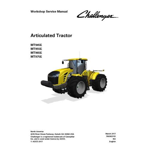
Table of contents

  • 1. General
    • 1.1 Safety information
    • 1.2 Serial number definition
    • 1.3 Proper disposal of waste
    • 1.4 Lubricant viscosities and refill capacities
    • 1.5 Service intervals
    • 1.6 Engine specifications - MT900E
    • 1.7 Torque specifications
    • 1.8 Machine specifications
  • 2. Engine, fuel, and exhaust system
    • 2.1 Engine maintenance
    • 2.2 Engine system components
    • 2.3 Flush and refill the cooling system
    • 2.4 Engine troubleshooting
    • 2.5 Fuel system components
    • 2.6 Exhaust system components
    • 2.7 SCR system
    • 2.8 Fluid specifications
    • 2.9 Safety instructions
    • 2.10 To the user
    • 2.11 Engine construction
    • 2.12 Technical data
    • 2.13 Liquid quality requirements
    • 2.14 Tightening torques
    • 2.15 Special tools
    • 2.16 Major maintenance and engine replacement
    • 2.17 Cylinder block
    • 2.18 Flywheel housing
    • 2.19 Cylinder head
    • 2.20 Valve mechanism
    • 2.21 Crankshaft
    • 2.22 Connecting rods and pistons
    • 2.23 Flywheel
    • 2.24 Timing gear assembly
    • 2.25 Belts
    • 2.26 Lubrication system
    • 2.27 Cooling system
    • 2.28 Air control system maintenance
    • 2.29 Fuel system
    • 2.30 SCR system
    • 2.31 Engine control system
    • 2.32 Terminal diagram
  • 3. Axles
    • 3.1 Axle system operation
    • 3.2 Differential lock system
    • 3.3 Axle lubrication
    • 3.4 Axle components
    • 3.5 Final drive disassembly
    • 3.6 Final drive assembly
    • 3.7 Differential disassembly
    • 3.8 Differential assembly
    • 3.9 Axle maintenance
    • 3.10 Axle testing and adjusting
    • 3.11 Axle comnponent specifications
  • 4. Frame and suspension
    • 4.1 Split the machine
    • 4.2 Connect the machine
    • 4.3 Replace the articulation bearing
    • 4.4 Frame repair
    • 4.5 Repair the frame by adding weld material and machining
    • 4.6 Articulation position sensor
    • 4.7 Specifications
  • 5. Steering system
    • 5.1 Steering system layout
    • 5.2 Steering system components
    • 5.3 Steering system operation
    • 5.4 Steering system disassembly and assembly
    • 5.5 Steering system test and adjust
    • 5.6 Steering system maintenance
  • 6. Drivetrain system
    • 6.1 Transmission system
    • 6.2 Transmission
    • 6.3 Drivetrain components
    • 6.4 Transmission troubleshooting
    • 6.5 Drivetrain system test and adjust
    • 6.6 Drive train maintenance
  • 7. Brake system
    • 7.1 Service and brake system operation
    • 7.2 Trailer brake system (optional)
    • 7.3 Service and parking brake components
    • 7.4 Electrical components of park brake system
    • 7.5 Position of electronic components for the parking brake system
    • 7.6 Brake system disassembly and assembly
    • 7.7 Brake system testing and adjusting
    • 7.8 Brake system maintenance
    • 7.9 Brake system specifications
  • 8. Compressed air system
    • 8.1 Air system operation
    • 8.2 Air system components
    • 8.3 Air system component specifications
    • 8.4 Troubleshoot the air dryer
    • 8.5 Air system maintenance
  • 9. Hydraulic system
    • 9.1 Implement hydraulic system introduction
    • 9.2 Implement hydraulic system components
    • 9.3 Hydraulic system disassembly and assembly
    • 9.4 Hydraulic system testing and adjusting
    • 9.5 Hydraulic system maintenance
    • 9.6 Hydraulic troubleshooting
  • 10. Electrical system
    • 10.1 General information
    • 10.2 Electrical system components
    • 10.3 Fuse panel
    • 10.4 Electrical system troubleshooting
    • 10.5 00 Engine module
    • 10.6 03 Transmission
    • 10.7 05 Armrest module
    • 10.8 19 Steering valve module
    • 10.9 161 Auxiliary valve 1 module
    • 10.10 162 Auxiliary valve 2 module
    • 10.11 163 Auxiliary valve 3 module
    • 10.12 164 Auxiliary valve 4 module
    • 10.13 165 Auxiliary valve 5 module
    • 10.14 166 Auxiliary valve 6 module
    • 10.15 171 Three-point hitch valve module
    • 10.16 175 Unassigned auxiliary valve module
    • 10.17 208 Front lighting module
    • 10.18 209 Roof lighting module
    • 10.19 210 Rear lighting module
  • 11. Cab
    • 11.1 Remove and install the cab
    • 11.2 Cab filtration
    • 11.3 Armrest
    • 11.4 Cab seat
    • 11.5 Cab switches
    • 11.6 Steering console
    • 11.7 Cab components
  • 12. Air conditioning and heating system
    • 12.1 Air conditioning and heating system
    • 12.2 Testing and adjusting
    • 12.3 Basic air conditioning system testing
    • 12.4 Manifold gauge set readings
    • 12.5 Checking the system pressure
    • 12.6 Refrigerant recovery
    • 12.7 Air conditioning and heating system components
    • 12.8 Heating and air conditioning troubleshooting
  • 13. Chassis
    • 13.1 Engine cover
    • 13.2 Fenders
    • 13.3 Extremity arms
    • 13.4 Test the machine lighting
  • 14. Wheels
    • 14.1 Wheel removal
    • 14.2 Wheel installation
    • 14.3 Wheel and counterweight re-torque
    • 14.4 Wheel special tooling
    • 14.5 Hub spacing
    • 14.6 Remove the hub and collet
    • 14.7 Install the hub and collet
  • 15. Implement drive system
    • 15.1 Power take-off
    • 15.2 Power take-off system
    • 15.3 Power take-off system testing and adjusting
  • 16. Implement lift system
    • 16.1 3-point linkage system introduction
    • 16.2 Position of hydraulic components
    • 16.3 3-point linkage control valve
    • 16.4 Position of electical components
    • 16.5 3-point linkage disassembly and assembly
    • 16.6 3-point linkage system testing and adjusting
    • 16.7 3-point linkage troubleshooting
  • 17. Attachments
    • 17.1 Drawbar
    • 17.2 Drawbar maintenance
    • 17.3 Ballasting
    • 17.4 Weight removal and installation
    • 17.5 Toolbox
    • 17.6 Special application hitch
    • 17.7 Tow cable
  • 18. Diagrams
    • 18.1 Hydraulic schematics
    • 18.2 Electrical schematics
    • 18.3 Connector location diagrams
  • 19. Special tools
    • 19.1 Axle special tools
  • Index

8 other products in the same category: