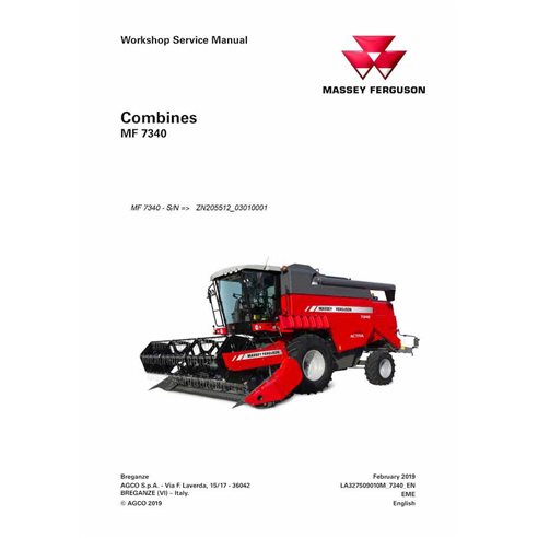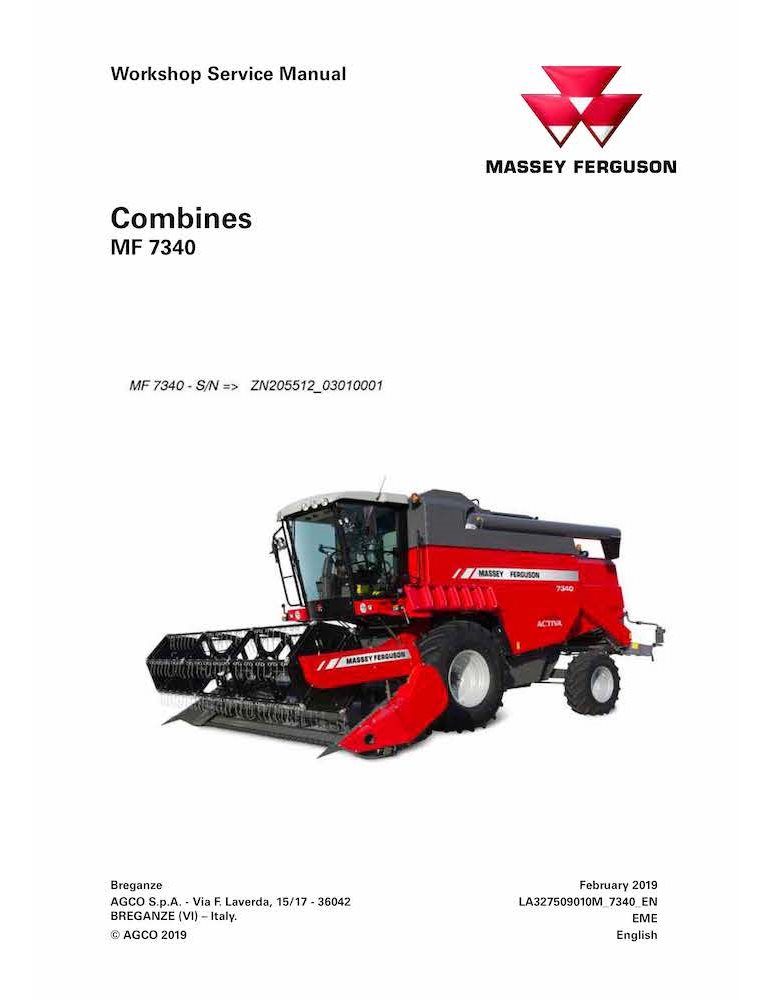
Massey Ferguson 7340 combine pdf workshop service manual
Format: PDF
Pages: 773
File size: 14.39 MB
Language: English
Models: MF7340

Table of Contents for MF-327509010M-WSM-EN manual
- 1. Preface
- 1.1 Introductory notes
- 1.2 Important warnings
- 1.3 Identification number
- 2. General Information - 00
- 2.1 General instructions
- 2.2 Safety precautions
- 2.3 Appropriate use
- 2.4 Technical specifications
- 2.5 Lubrication
- 2.6 Service intervals
- 2.7 Combine dimensions
- 2.8 Tracks with runners
- 2.9 Tire equipment- front axle
- 2.10 Tire equipment - rear axle
- 2.11 Tire equipment - Version with half-tracks on front axle
- 2.12 Drive trains – left-hand side
- 2.13 Drive trains – right-hand side
- 2.14 Location of electrical/electronic/hydraulic components
- 2.15 Screw tightening torques (Nm)
- 2.16 Units of measurement
- 3. Engine - 10
- 3.1 Location of the EEM4 ECU engine serial number
- 3.2 Technical specifications
- 3.3 Main components
- 3.4 Main electrical components
- 3.5 Troubleshooting
- 3.6 Error Codes
- 3.7 Engine power limits for emission faults
- 3.8 Engine supply
- 3.9 Injectors
- 3.10 High-pressure pump - Disassembly and refitting
- 3.11 Rail
- 3.12 Fuel filters on the engine - Replace
- 3.13 Prefilter / water separator - Replace
- 3.14 Prefilter / water separator - Replace (optional filter)
- 3.15 Bleeding the fuel system with the hand pump
- 3.16 Measuring the fuel feed pressure
- 3.17 Fuel tank
- 3.18 Intake and exhaust system
- 3.19 Engine air filter
- 3.20 Selective catalytic reduction (SCR) system
- 3.21 SCR System components
- 3.22 Feed module - A84
- 3.23 Main filter - Replace
- 3.24 DEF dosing module - A85
- 3.25 Ejector temperature sensor
- 3.26 NOx sensor
- 3.27 Exhaust system
- 3.28 SCR System - Recommended equipment when carrying out checks
- 3.29 Error code diagnostics
- 3.30 Engine lubrication
- 3.31 Engine oil and filter
- 3.32 Closed crankcase ventilation (CCV)
- 3.33 Engine cooling system
- 3.34 Lubrication oil cooler
- 3.35 Engine cooling pump belt
- 3.36 Radiator fan drive belt
- 3.37 Cooling circuit
- 3.38 Radiators
- 3.39 Rotary Screen and Dust Aspirator
- 3.40 Engine control unit
- 3.41 Precautions for welding operations
- 3.42 Engine control system sensors
- 4. Drive transmission - 14
- 4.1 Specifications
- 4.2 Tightening torques and sectional view
- 4.3 Operation description
- 4.4 Troubleshooting
- 4.5 Drive transmission
- 5. Transmission - 21
- 5.1 Specifications
- 5.2 Tightening torques and sections
- 5.3 Operation description
- 5.4 Troubleshooting
- 5.5 Tools
- 5.6 Gearbox
- 5.7 Gearbox internal components
- 5.8 Differential
- 5.9 Gear engagement flexible tie rods
- 5.10 Gear engagement rods
- 6. Front drive axle - 25
- 6.1 Specifications
- 6.2 STD 8 final drive cutaway view
- 6.3 Tools
- 6.4 STD 8 lateral final drive
- 6.5 STD 8 final drive housing
- 7. Hydrostatic transmission - 29
- 7.1 Specifications
- 7.2 Hydrostatic circuit diagram
- 7.3 Hydraulic symbols
- 7.4 Hydrostatic traction troubleshooting
- 7.5 Hydrostatic pump transmission
- 7.6 Radiator RD and oil tank
- 7.7 Hydrostatic system
- 7.8 Sauer pump and motor
- 7.9 Pump 90L100 - PM4
- 7.10 Motor 90M100 - MR2
- 7.11 Pressure check (Sauer 90L100 - PM4)
- 7.12 MR2 engine assembly - R/I
- 7.13 Pump assembly90L100 PM4 - R/I
- 7.14 Sauer pump and motor components
- 7.15 Manually operated pump servo control VB14 (Sauer 90L100)
- 7.16 Pump front seal (Sauer 90L100) - Replace
- 7.17 Sauer pump 90L100 valves - V13, V14a and V14b
- 7.18 Motor front seal - Replace
- 8. Brakes - 33
- 8.1 Specifications
- 8.2 Tightening torques and sections
- 8.3 Brake pedal stroke adjustment in case of replacement of service brake master cylinder
- 8.4 Operation description
- 8.5 Troubleshooting
- 8.6 Parking brake
- 8.7 Service brake circuit - Air bleeding
- 8.8 Breaking balancer - D./A.
- 8.9 Brake hydraulic pump - R./I.
- 8.10 Brake hydraulic pump, removed - D./A.
- 8.11 Brake callipers - R./I.
- 8.12 Brake pads (set) - Replacement
- 8.13 Brake disc - R./I.
- 9. Hydraulic system - 35
- 9.1 Specifications
- 9.2 Hydraulic components - AC
- 9.3 Hydraulic components - FL
- 9.4 Hydraulic components - HV
- 9.5 Hydraulic components - PM
- 9.6 Hydraulic components - TK
- 9.7 Hydraulic components - VB
- 9.8 Cylinder head and reel positioning hydraulic circuit
- 9.9 Crop elevator lifting and lowering
- 9.10 Reel lifting and lowering
- 9.11 Reel forward and retraction movement
- 9.12 Engagement hydraulic circuit
- 9.13 Grain unloading auger opening/closing
- 9.14 Cylinder revolution increase/decrease
- 9.15 Engagement and disengagement of straw chopper
- 9.16 Hydraulic cylinders
- 9.17 Circuit pressure measurement
- 10. Steering - 41
- 10.1 Specifications
- 10.2 Steering linkage
- 10.3 Steering cylinder
- 10.4 Hydrostatic power steering hydraulic circuit
- 10.5 Hydrostatic power steering
- 11. Axles and wheels - 44
- 11.1 Specifications
- 11.2 Front axle
- 11.3 Wheel hub - R./I.
- 11.4 Steering knuckle - Replace
- 11.5 Rear axle position
- 12. Cab air conditioning system - 50
- 12.1 Specifications
- 12.2 Safety Precautions
- 12.3 Component location
- 12.4 Air conditioning circuit
- 12.5 Air conditioning in the cab
- 12.6 Heating
- 12.7 Cab air filters
- 12.8 Evaporator
- 12.9 Condenser
- 12.10 Dehydrator filter
- 13. Electrical system - 55
- 13.1 Electrical components
- 13.2 Steering column
- 13.3 Multifunction lever
- 13.4 Instrument panel
- 13.5 Cab
- 13.6 What is a CAN system?
- 13.7 A82 - A83 - NOx sensor controller
- 13.8 A84 - DEF feed module
- 13.9 A85 - DEF dosing module
- 13.10 A99 - Engine controller
- 13.11 A142 - Display
- 13.12 A163 - OPS warning horn timer
- 13.13 B7 - Fuel level sensor
- 13.14 B30 - Tachometer sensor
- 13.15 B36 - Straw chopper revolution sensor
- 13.16 B38 - Fanning mill revolution sensor
- 13.17 B39 - Crop elevator revolution sensor
- 13.18 B40 - Tailings elevator revolution sensor
- 13.19 B44 - Cylinder revolution sensor
- 13.20 B60 - B61 - Sieve performance sensors
- 13.21 B62 - B63 - Straw walker performance sensors
- 13.22 B102 - DEF level/temperature sensor
- 13.23 B103 - Outside air temperature sensor
- 13.24 S6 - Microswitch for park brake lever position
- 13.25 S53 - Operator presence switch
- 13.26 Electrical diagrams
- 14. Attachments/Headers - 58
- 14.1 Specifications
- 14.2 Cutting table reel
- 14.3 Threshing unit
- 14.4 Blade drive transmission housing lower bearing - Replace
- 14.5 Table auger
- 14.6 Feed auger adjustment
- 14.7 Adjustment of retractable fingers - L-type cutting table
- 14.8 Central shaft for retractable finger support - Replace
- 14.9 Cutting table drive transmission
- 15. Product feeding - 60
- 15.1 Specifications
- 15.2 Floating roller and feeder chain
- 15.3 Header drive transmission
- 15.4 Feeder drive transmission
- 15.5 Front elevator upper shaft
- 15.6 Additional support for the elevator housing upper shaft (maize)
- 15.7 Attaching the cutting table
- 15.8 Removing the table
- 15.9 Adjustment of cutting table ground clearance
- 15.10 Reverse drive system
- 16. Threshing - 66
- 16.1 Specifications
- 16.2 Stone trap assembly removal/refitting
- 16.3 Concave
- 16.4 Wheat concave
- 16.5 Sectional concave
- 16.6 Universal wheat/maize concave
- 16.7 Spike-toothed Cylinder/Concave (for rice)
- 16.8 Unblocking the threshing drum
- 16.9 Cylinder bar
- 16.10 Cylinder housing inspection doors
- 16.11 Concave rake
- 16.12 Thresher PTO
- 16.13 Cylinder variator
- 16.14 Sensor for threshing drum revolution counter
- 16.15 Rear beater
- 16.16 Cylinder standard settings
- 17. Separation - 72
- 17.1 Specifications
- 17.2 Straw walker and shafts
- 17.3 Fitting straw risers
- 18. Straw chopper - 73
- 18.1 Specifications
- 18.2 Transmission type
- 18.3 Straw chopper control and transmission drive
- 18.4 Adjustment of the straw chopper rotor knives
- 18.5 Counter-knives
- 18.6 Chopping quality
- 18.7 Using the straw chopper on maize and sunflower
- 18.8 Straw chopper bearings - Replacement
- 18.9 Engagement of straw chopper
- 19. Cleaning - 74
- 19.1 Specifications
- 19.2 Cleaning drive transmission
- 19.3 Box transmission
- 19.4 Main transmission assembly - Removing and refitting
- 19.5 Box control shaft
- 19.6 Feed box
- 19.7 Upper shaker shoe
- 19.8 Lower shaker shoe
- 19.9 Adjustable sieves
- 19.10 Fanning mill variator
- 19.11 Fan housing
- 19.12 Basic fan setting for the main crops
- 20. Grain tank - 80
- 20.1 Specifications
- 20.2 Crop elevator to the tank
- 20.3 General information
- 20.4 Grain tank unloading auger
- 20.5 Unloading auger drive belt
- 20.6 Sensor to measure tank filling
- 20.7 Doors for Grain Tank Maintenance and Cleaning
- 20.8 Vertical auger tank drain door
- 20.9 Tank bottom door
- 20.10 Grain Tank Cover
- 20.11 Grain unloading auger
- 20.12 Angle gear housings
- 21. Conversion
- 21.1 Grain-maize conversion
- 21.2 Machines with a straw chopper
High-Quality PDF Service Manuals for Professional Repair
Our Service Manuals are comprehensive digital products delivered in convenient PDF formats, providing the exact technical data required to maintain, repair, and troubleshoot your equipment. Whether you are a fleet owner or a professional technician, having a dedicated PDF service manual ensures you have instant access to factory-spec information.
What is Included in Our Service Manuals?
Every repair and service manual we provide is structured to offer a professional-grade approach to machinery maintenance. When you download a manual, you gain access to:
-
Detailed Technical Specifications: Precise clearances, capacities, and settings.
-
Step-by-Step Procedures: Guided instructions for assembly, disassembly, and component repair.
-
High-Resolution Diagrams: Clear schematics and exploded views for easy parts identification.
-
Diagnostic Flowcharts: Logic-based troubleshooting to identify faults quickly.
-
Safety & Compliance Guidelines: Essential precautions to ensure safe operation and regulatory compliance.
Why Choose a Digital PDF Service Manual?
A Service Manual is more than just a book; it is an essential tool for maximizing the lifetime of complex machinery. By using our digital service manuals, technicians can accurately diagnose problems, perform precision repairs, and reduce costly downtime.
Unlike paper alternatives, our PDF manuals are searchable, allow for high-quality zooming on intricate diagrams, and can be accessed on any device—from the workshop floor to the field.